ATMEGA103 View Datasheet(PDF) - Atmel Corporation
Part Name
Description
Manufacturer
ATMEGA103 Datasheet PDF : 10 Pages
| |||
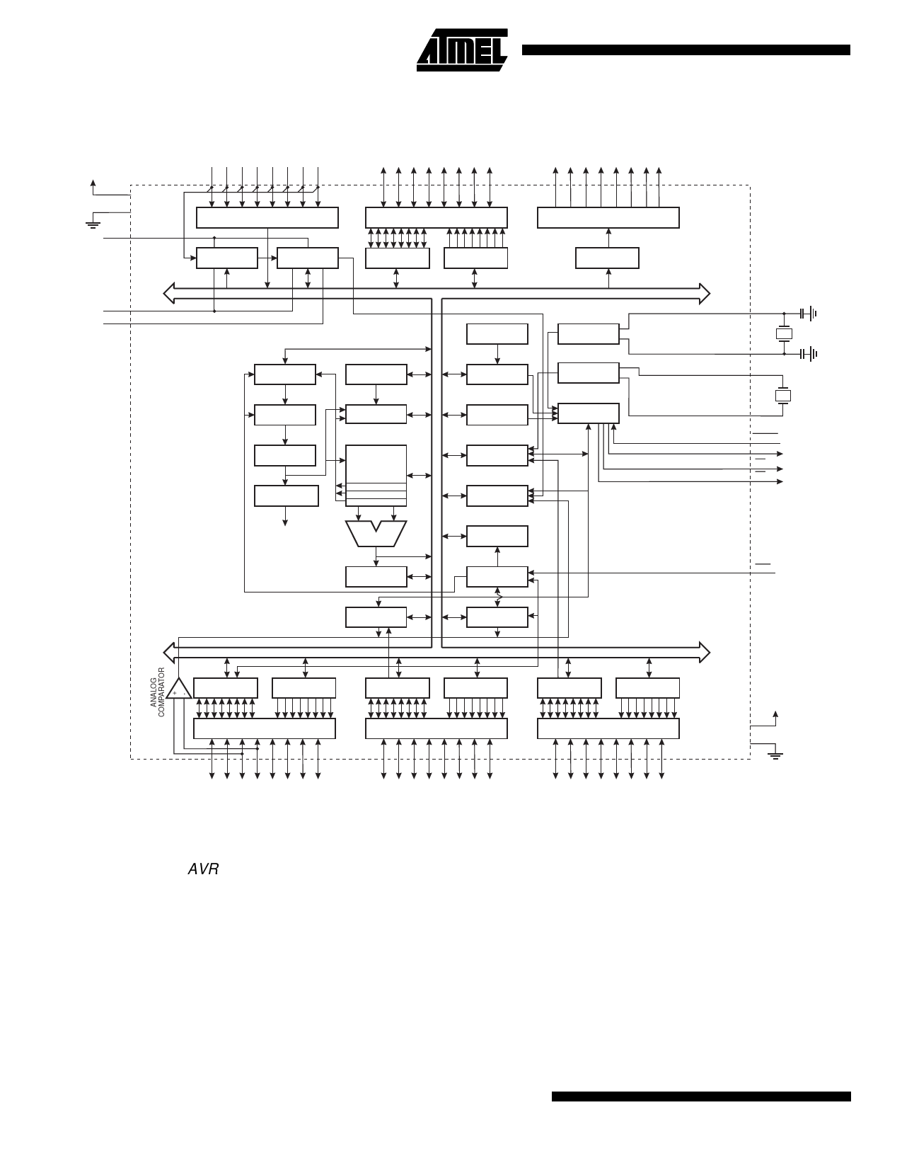
Block Diagram
Figure 1. The ATmega603/103 Block Diagram
PF0 - PF7
PA0 - PA7
PC0 - PC7
VCC
GND
AVCC
AGND
AREF
PORTF BUFFERS
ANALOG MUX
ADC
PORTA DRIVER/BUFFERS
PORTC DRIVERS
DATA REGISTER
PORTA
DATA DIR.
REG. PORTA
DATA REGISTER
PORTC
8-BIT DATA BUS
INTERNAL
OSCILLATOR
OSCILLATOR
PROGRAM
COUNTER
PROGRAM
FLASH
STACK
POINTER
SRAM
WATCHDOG
TIMER
MCU CONTROL
REGISTER
OSCILLATOR
TIMING AND
CONTROL
INSTRUCTION
REGISTER
INSTRUCTION
DECODER
CONTROL
LINES
GENERAL
PURPOSE
REGISTERS
X
Y
Z
ALU
TIMER/
COUNTERS
INTERRUPT
UNIT
EEPROM
STATUS
REGISTER
PROGRAMMING
LOGIC
SPI
UART
XTAL1
XTAL1
TOSC2
TOSC1
RESET
ALE
WR
RD
PEN
DATA REGISTER
PORTE
DATA DIR.
REG. PORTE
PORTE DRIVER/BUFFERS
DATA REGISTER
PORTB
DATA DIR.
REG. PORTB
PORTB DRIVER/BUFFERS
DATA REGISTER
PORTD
DATA DIR.
REG. PORTD
PORTD DRIVER/BUFFERS
VCC
GND
PE0 - PE7
PB0 - PB7
PD0 - PD7
Description
The ATmega603/103 is a low-power CMOS 8-bit microcon-
troller based on the AVR enhanced RISC architecture. By
executing powerful instructions in a single clock cycle, the
ATmega603/103 achieves throughputs approaching 1
MIPS per MHz allowing the system designer to optimize
power consumption versus processing speed.
The AVR core is based on an enhanced RISC architecture
that combines a rich instruction set with 32 general purpose
working registers. All the 32 registers are directly con-
nected to the Arithmetic Logic Unit (ALU), allowing two
independent registers to be accessed in one single instruc-
tion executed in one clock cycle. The resulting architecture
is more code efficient while achieving throughputs up to ten
times faster than conventional CISC microcontrollers.
The ATmega603/103 provides the following features:
64K/128K bytes of In-system Programmable Flash, 2K/4K
bytes EEPROM, 4K bytes SRAM, 32 general purpose I/O
lines, 8 Input lines, 8 Output lines, 32 general purpose
working registers, 4 flexible timer/counters with compare
modes and PWM, UART, programmable Watchdog Timer
with internal oscillator, an SPI serial port and three software
selectable power saving modes. The Idle Mode stops the
CPU while allowing the SRAM, timer/counters, SPI port
and interrupt system to continue functioning. The Power
2 ATmega603(L) and ATmega103(L)
Share Link: 