PEEL22CV10AZ-25 View Datasheet(PDF) - Unspecified
Part Name
Description
Manufacturer
PEEL22CV10AZ-25 Datasheet PDF : 10 Pages
| |||
PEEL™ 22CV10AZ
In addition to emulating the four PAL-type output structures
(configurations 3, 4, 9, and 10), The macrocell provides
eight additional configurations. Equivalent circuits for the
twelve macrocell configurations are illustrated in Figure 22.
These structures are accessed by specifying the
PEEL™22CV10A+ or PEEL™22CV10A++ option when
assembling the equations.
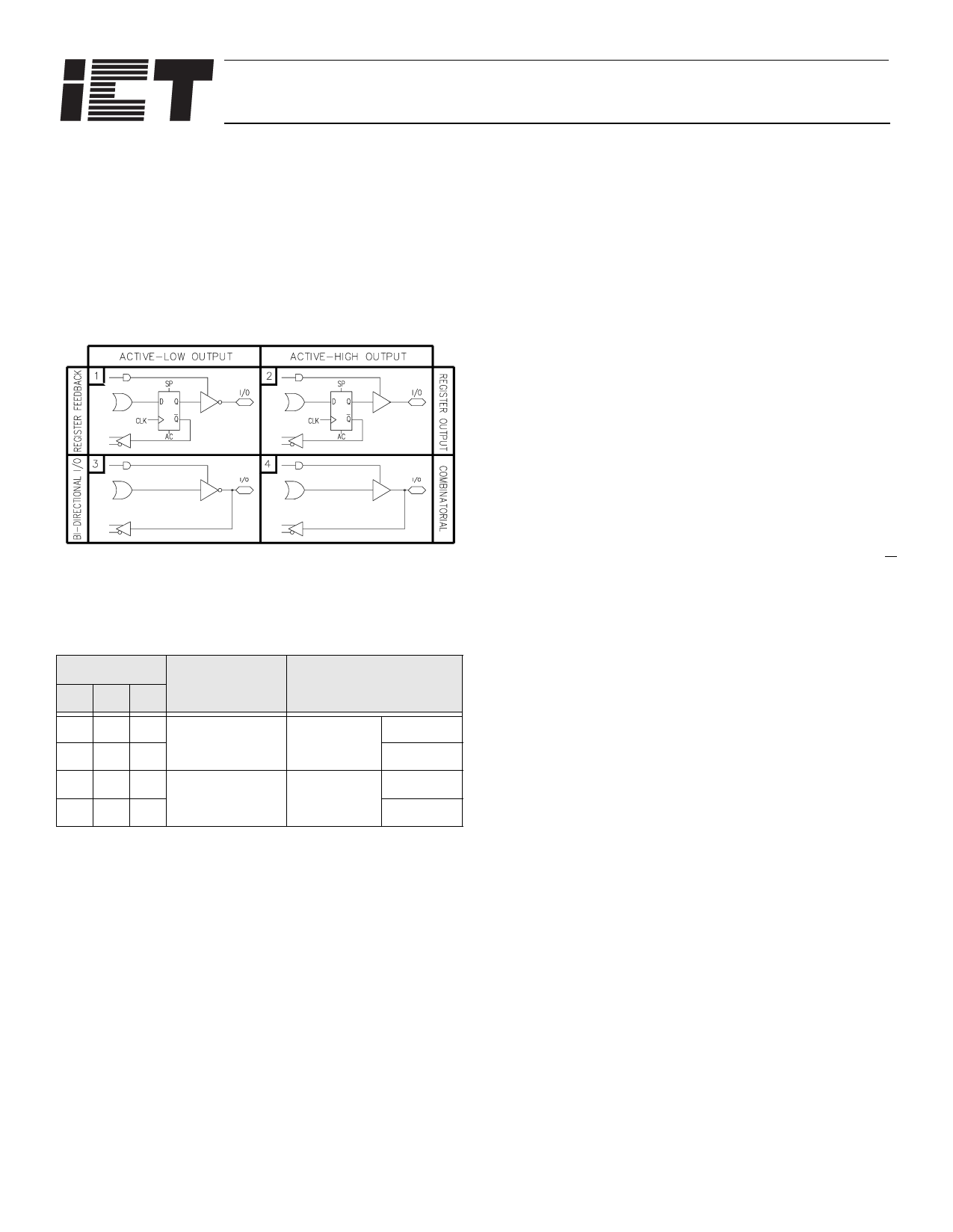
Figure 21 Equivalent Circuits for the Four
Configurations of the I/O Macrocell
Table 1. PEEL™22CV10A Macrocell
Configuration Bits
Configuration Input/Feedback
#AB
Select
Output Select
100
210
Register
Feedback
Register
Active Low
Active High
301
4
Bi-Directional
I/O
Combinatorial
Active Low
Active High
When creating a PEEL™ device design, the desired mac-
rocell configuration is generally specified explicitly in the
design file. When the design is assembled or compiled, the
macrocell configuration bits are defined in the last lines of
the JEDEC programming file.
Output Type
The signal from the OR array can be fed directly to the out-
put pin (combinatorial function) or latched in the D-type flip-
flop (registered function). The D-type flip-flop latches data
on the rising edge of the clock and is controlled by the glo-
bal preset and clear terms. When the synchronous preset
term is satisfied, the Q output of the register is set HIGH at
the next rising edge of the clock input. Satisfying the asyn-
chronous clear sets Q LOW, regardless of the clock state. If
both terms are satisfied simultaneously, the clear will over-
ride the preset.
Output Polarity
Each macrocell can be configured to implement active-high
or active-low logic. Programmable polarity eliminates the
need for external inverters.
Output Enable
The output of each I/O macrocell can be enabled or dis-
abled under the control of its associated programmable out-
put enable product term. When the logical conditions
programmed on the output enable term are satisfied, the
output signal is propagated to the I/O pin. Otherwise, the
output buffer is switched into the high-impedance state.
Under the control of the output enable term, the I/O pin can
function as a dedicated input, a dedicated output, or a bi-
directional I/O. Opening every connection on the output
enable term will permanently enable the output buffer and
yield a dedicated output. Conversely, if every connection is
intact, the enable term will always be logically false and the
I/O will function as a dedicated input.
Input/Feedback Select
When configuring an I/O macrocell to implement a regis-
tered function (configurations 1 and 2 in Figure 21), the Q
output of the flip-flop drives the feedback term. When con-
figuring an I/O macrocell to implement a combinatorial out-
put (configurations 3 and 4 in Figure 21), the feedback term
is taken from the I/O pin. In this case, the pin can be used
as a dedicated input or a bi-directional I/O (Refer also to
Table 1.)
Programmable Clock Options
A unique feature of the PEEL™22CV10AZ is a program-
mable clock multiplexer that allows you to select true or
complement forms of either the input pin or a product-term
clock source. This feature can be accessed by specifying
the PEEL™22CV10A++ option when assembling the equa-
tions.
4 of 10
Share Link: 