ADM1020 View Datasheet(PDF) - Analog Devices
Part Name
Description
Manufacturer
ADM1020 Datasheet PDF : 12 Pages
| |||
ADM1020
ALERT OUTPUT
The ALERT output goes low whenever an out-of limit measure-
ment is detected, or if the remote temperature sensor is open-
circuit. It is an open-drain and requires a 10 kΩ pull-up to VDD.
Several ALERT outputs can be wire-ANDED together, so that
the common line will go low if one or more of the ALERT out-
puts goes low.
The ALERT output can be used as an interrupt signal to a
processor, or it may be used as an SMBALERT. Slave devices
on the SMBus can not normally signal to the master that they
want to talk, but the SMBALERT function allows them to do so.
One or more ALERT outputs are connected to a common
SMBALERT line connected to the master. When the
SMBALERT line is pulled low by one of the devices, the
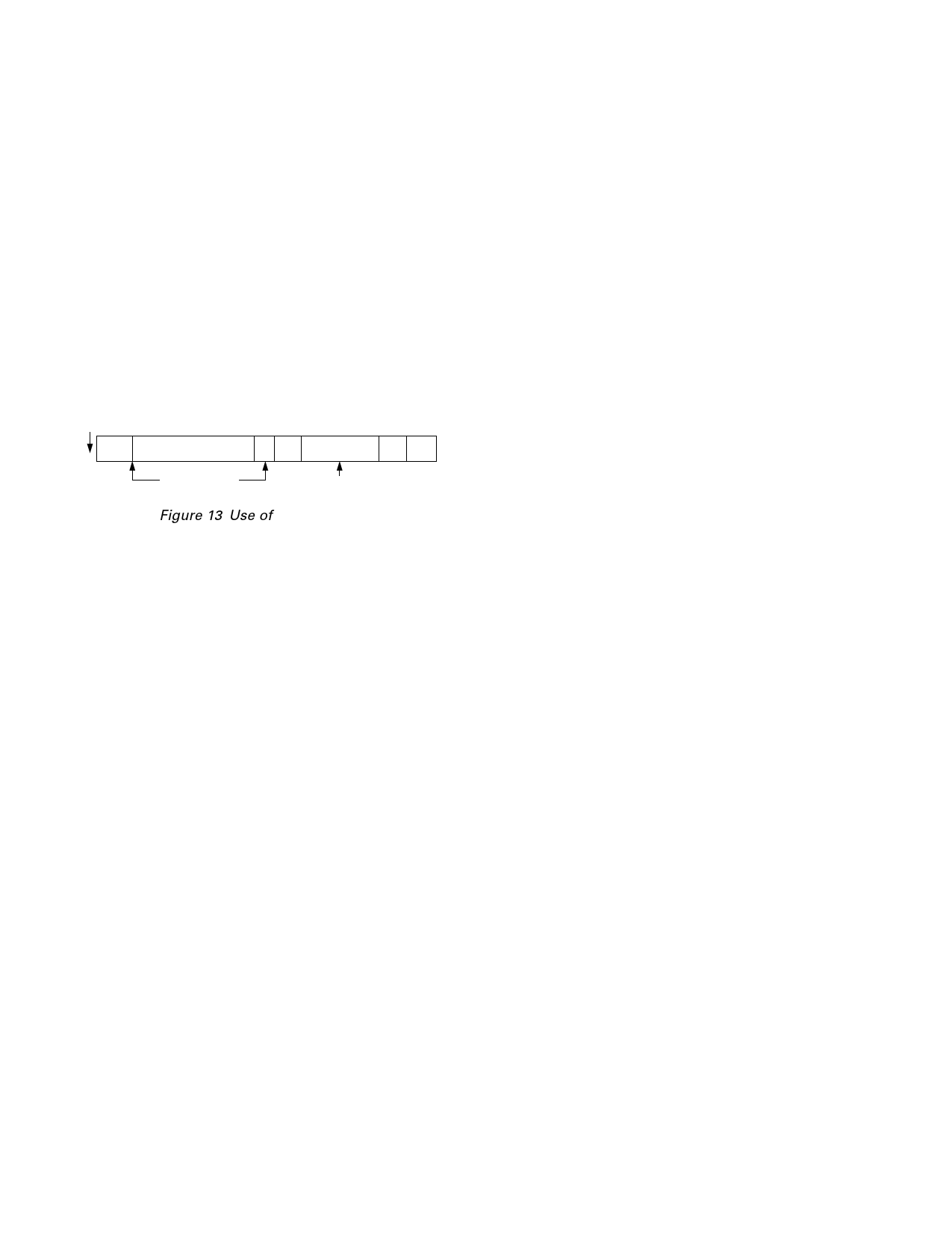
following procedure occurs as illustrated in Figure 13.
MASTER
RECEIVES
SMBALERT
START
ALERT
RESPONSE ADDRESS
RD ACK
DEVICE
ADDRESS
NO
ACK
STOP
MASTER SENDS
ARA AND READ
COMMAND
DEVICE SENDS
ITS ADDRESS
Figure 13 Use of SMBALERT
1. SMBALERT pulled low.
2. Master initiates a read operation and sends the Alert Re-
sponse Address (ARA = 0001 100). This is a general call
address that must not be used as a specific device address.
3. The device whose ALERT output is low responds to the
Alert Response Address and the master reads its device ad-
dress. The address of the device is now known and it can be
interrogated in the usual way.
4. If more than one device’s ALERT output is low, the one with
the lowest device address will have priority, in accordance
with normal SMBus arbitration.
5. Once the ADM1020 has responded to the Alert Response
Address, it will reset its ALERT output, provided that the
error condition that caused the ALERT no longer exists. If
the SMBALERT line remains low, the master will send ARA
again, and so on until all devices whose ALERT outputs were
low have responded.
LOW POWER STANDBY MODES
The ADM1020 can be put into a low power standby mode by
setting Bit 6 of the Configuration Register. With Bit 6 low the
ADM1020 operates normally. When Bit 6 is high, the ADC is
inhibited, any conversion in progress is terminated without
writing the result to the corresponding value register.
The SMBus is still enabled. Power consumption in the standby
mode is reduced to less than 10 µA if there is no SMBus activ-
ity, or 100 µA if there are clock and data signals on the bus.
When Bit 6 is set , a one-shot conversion of both channels can
be initiated by writing XXh to the One-Shot Register (address
0Fh).
SENSOR FAULT DETECTION
The ADM1020 has a fault detector at the D+ input that detects
if the external sensor diode is open-circuit. This is a simple
voltage comparator that trips if the voltage at D+ exceeds
VCC – 1 V (typical). The output of this comparator is checked
when a conversion is initiated, and sets Bit 2 of the Status Reg-
ister if a fault is detected.
If the remote sensor voltage falls below the normal measuring
range, for example due to the diode being short-circuited, the
ADC will output –128 (1000 0000). Since the normal operating
temperature range of the device only extends down to –55°C,
this output code should never be seen in normal operation, so it
can be interpreted as a fault condition. Since it will be outside
the power-on default low temperature limit (–55°C) and any
low limit that would normally be programmed, a short-circuit
sensor will cause an SMBus alert.
In this respect the ADM1020 differs from and improves upon,
competitive devices that output zero if the external sensor goes
short-circuit. These devices can misinterpret a genuine 0°C
measurement as a fault condition.
If the external diode channel is not being used and it is shorted
out, the resulting ALERT may be cleared by writing 80h
(–128°C) to the low limit register.
APPLICATIONS INFORMATION
FACTORS AFFECTING ACCURACY
Remote Sensing Diode
The ADM1020 is designed to work with substrate transistors
built into processors, or with discrete transistors. Substrate
transistors will generally be PNP types with the collector con-
nected to the substrate. Discrete types can be either PNP or
NPN, connected as a diode (base shorted to collector). If an
NPN transistor is used then the collector and base are connected
to D+ and the emitter to D–. If a PNP transistor is used then
the collector and base are connected to D– and the emitter
to D+.
The user has no choice in the case of substrate transistors but if
a discrete transistor is used the best accuracy will be obtained by
choosing devices according to the following criteria:
1. Base-emitter voltage greater than 0.25 V at 6 µA, at the high-
est operating temperature.
2. Base-emitter voltage less than 0.95 V at 100 µA, at the lowest
operating temperature.
3. Base resistance less than 100 Ω.
4. Small variation in hFE (say 50 to 150) which indicates tight
control of VBE characteristics.
Transistors such as 2N3904, 2N3906 or equivalents in SOT-23
package are suitable devices to use.
–10–
REV. 0
Share Link: 