MC13281AP View Datasheet(PDF) - Motorola => Freescale
Part Name
Description
Manufacturer
MC13281AP Datasheet PDF : 12 Pages
| |||
MC13280AY
MC13281B MC13281A
Pin
Pin
1
1
3
3
5
5
2
2
Name
R
Subcontrast
Control
G
Subcontrast
Control
B
Subcontrast
Control
R Input
4
4
G Input
6
6
B Input
MC13280AY MC13281A/B
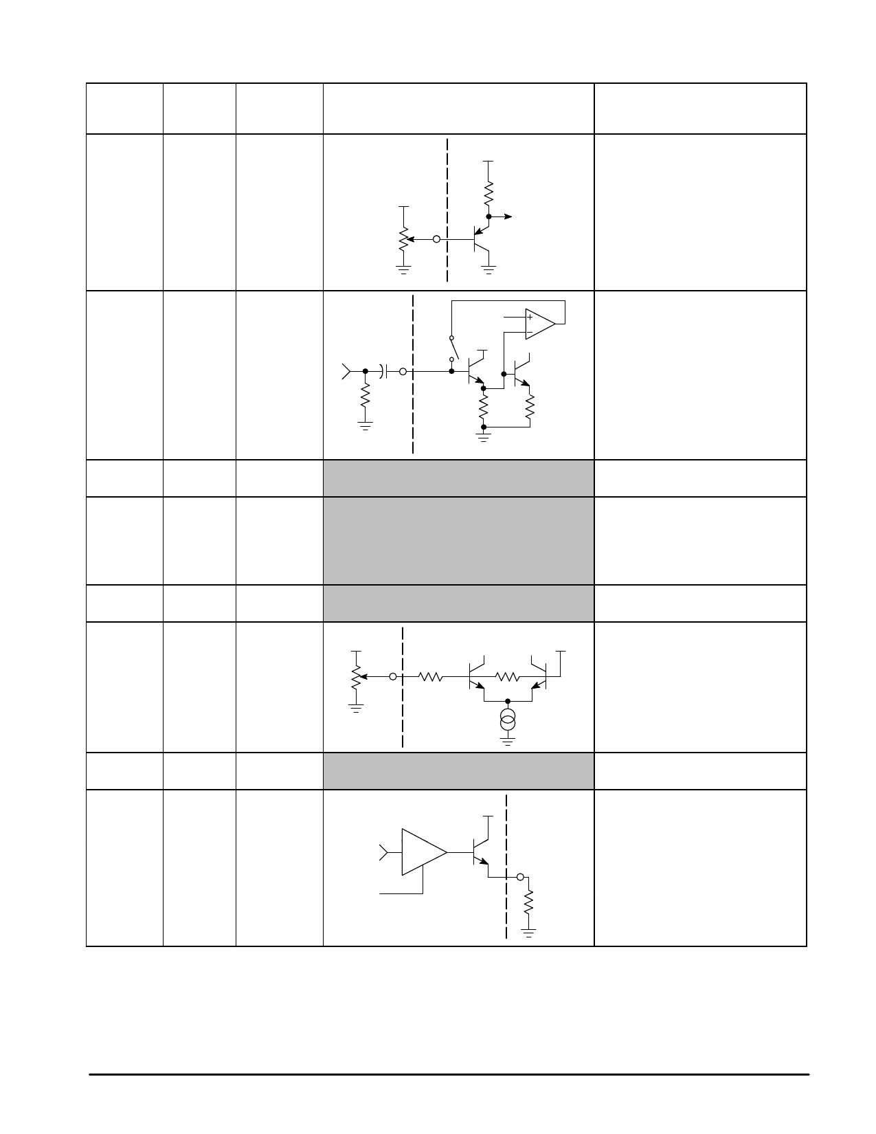
PIN FUNCTION DESCRIPTION
Equivalent Internal Circuit
VCC
5.0 V
50 k
Vref
0.1
Clamp 5.0 V
75 Ω
10 k
1.0 k
Description
These pins provides a maximum of
26 dB attenuation to vary the gain of
each video amplifier separately.
Input voltage is from 0 to 5.0 V.
Increasing the voltage will increase
the contrast level.
The input coupling capacitor is used
for input clamping storage. The
maximum source impedance is 100 Ω.
Input polarity of the video signal is
positive.
Nominal 0.7 Vpp input signal is
recommended (maximum 1.0 Vpp).
7
7
Ground
Ground pin. Connect to a clean, solid
ground.
N/A
8
N/C
Connected to ground.
10
N/C
11
N/C
12
N/C
8
9
VCC
Connect to 8.0 Vdc supply, ±5%.
Decoupling is required at this pin.
9
13
Contrast
5.0 V
Overall Contrast Control for the three
2.5 V
channels.
42 k
2.0 k
The input range is 0 V to 5.0 V. An
increase of voltage increases the
contrast.
10
14
Fast
Commutate
11
15
B Emitter
Output
15
19
G Emitter
Video
Signal
Output
Contrast
18
22
R Emitter
Output
Must be connected to ground.
VCC
The video outputs are configured as
emitter–followers with a driving
capability of about 15 mA each.
The dc voltage at these three emitters
is set to 1.2 V (black level).
RE = 330
Typical
The dc current through the output
stage is determined by the emitter
resistors (typically 330 Ω).
4
MOTOROLA ANALOG IC DEVICE DATA
Share Link: 