MC13281BP View Datasheet(PDF) - Motorola => Freescale
Part Name
Description
Manufacturer
MC13281BP Datasheet PDF : 12 Pages
| |||
MC13280AY MC13281A/B
FUNCTIONAL DESCRIPTION
The MC13280AY and MC13281A/B are composed of
three video amplifiers, clamping and blanking circuitry with
contrast and subcontrast controls. Each video amplifier is
designed to have a –3.0 dB bandwidth of 100 MHz
(MC13281, 80 MHz for the MC13280) with a gain of up to
about 5.6 V/V, or 15 dB.
Video Input
The video input stages are high impedance and designed
to accept a maximum signal of 1.0 Vpp with 75 Ω termination
(typically) provided externally. During the clamping period, a
current is provided to the input capacitor by the clamping
circuit which brings the input to a proper dc level (nominal
2.0 V). The blanking and clamping signals are to be provided
externally, with their thresholds at 1.25 V and 3.75 V,
respectively.
Video Output
The video output stages are configured as emitter–
followers, with a driving capability of about 15 mA for each
channel. The dc voltage at these three emitters is set to 1.2 V
(black level). The dc current through each output stage is
determined by the emitter resistor (typically 330 Ω).
Contrast Control
The contrast control varies the gain of three video
amplifiers from a minimum of 0.3 V/V to a maximum of
5.6 V/V when all subcontrast levels are set to 5.0 V.
Subcontrast Control
Each subcontrast control provides a maximum of 26 dB
attenuation on each video amplifier separately.
Clamp Pulse Input
The clamping pulse is provided externally, and the pulse
width must be no less than 500 ns.
Blank Pulse Input
The blanking pulse is used to blank the video signal during
the horizontal sync period, or used as a control pin for video
mute function.
Fast Commutate
This pin should be connected to ground.
Power Supplies
VCC and Video VCC supplies are to be 8.0 V ±5%.
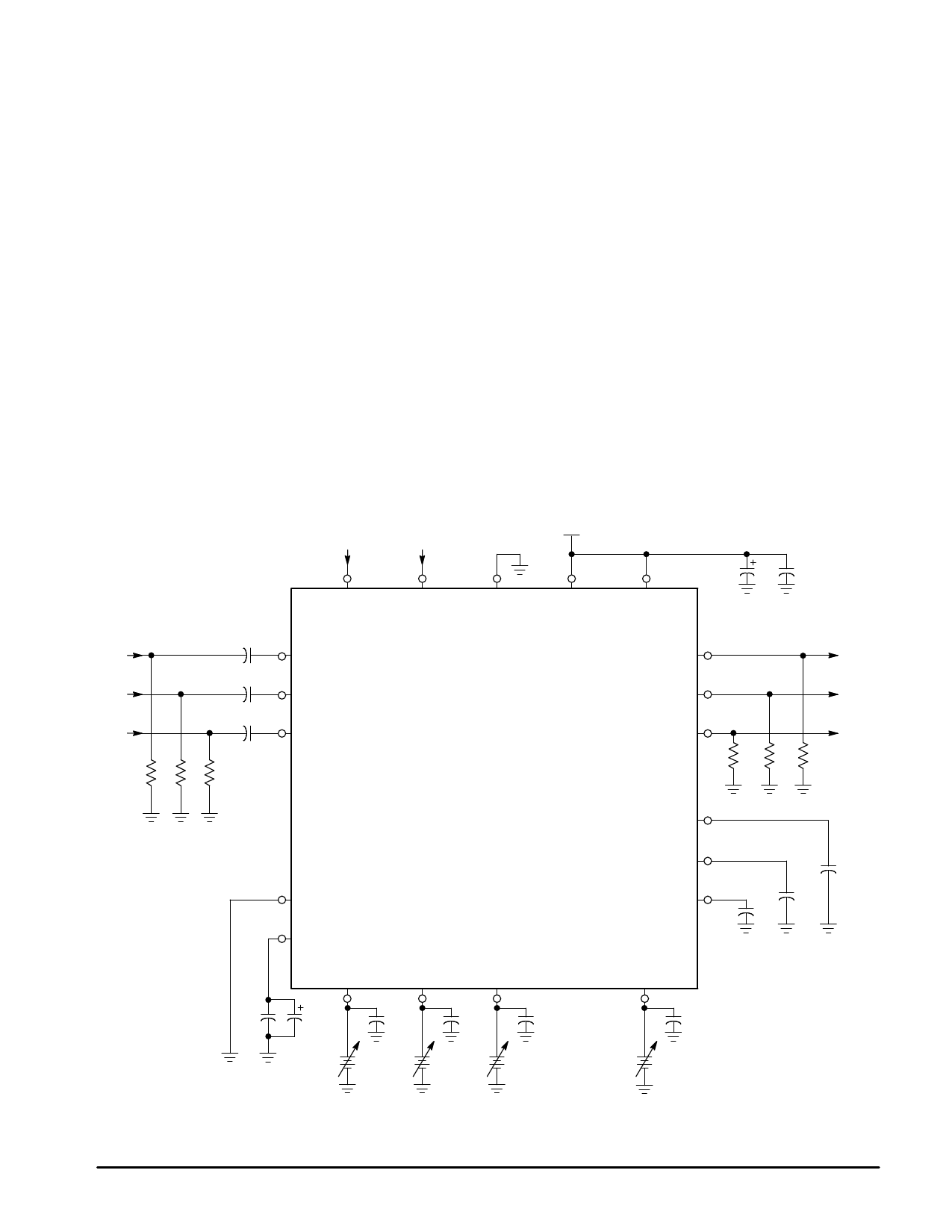
C1
R Input
0.1
C2
G Input
0.1
C3
B Input
0.1
R1 R2 R3
75 75 75
Figure 2. Test Circuit
Blank
Clamp
8.0 V
Input
Input
Blank
R Input
G Input
B Input
Clamp
Fast
Commutate
Video
VCC
MC13280AY
MC13281A/B
C14
C15
47 µF
0.1
VCC
R Emitter
G Emitter
B Emitter
R4
330
R5 R6
330 330
R Output
G Output
B Output
R Clamp
Gnd
V5
Subcontrast Control
R
G
B
C4
C5
C6
C7
C8
0.1
10 µF
0.1
0.1
0.1
5.0 V
5.0 V
5.0 V
G Clamp
B Clamp
Contrast
C13
0.1
C12
0.1
C11
0.1
Clamp Capacitor
C10
0.1
5.0 V
6
MOTOROLA ANALOG IC DEVICE DATA
Share Link: 