BTS7751G View Datasheet(PDF) - Infineon Technologies
Part Name
Description
Manufacturer
BTS7751G Datasheet PDF : 16 Pages
| |||
BTS 7751 G
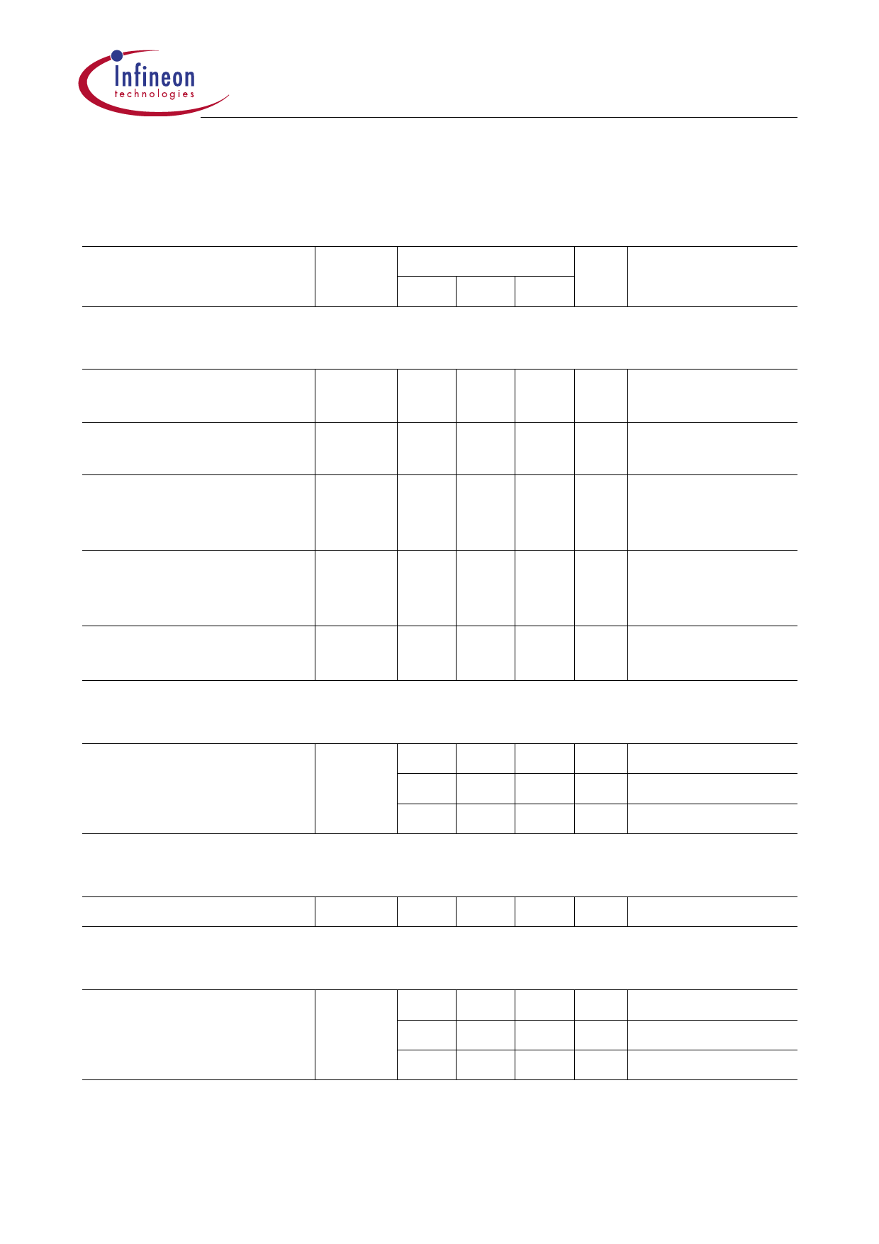
3.3 Electrical Characteristics (cont’d)
ISH1 = ISH2 = ISL1 = ISL2 = 0 A; – 40 °C < Tj < 150 °C; 8 V < VS < 18 V
unless otherwise specified
Parameter
Symbol Limit Values Unit Test Condition
min. typ. max.
Output stages
Inverse diode of high-side VFH
–
switch; Forward-voltage
Inverse diode of low-side VFL
–
switch; Forward-voltage
Static drain-source
R – DS ON H
on-resistance of high-side
switch
Static drain-source
on-resistance of low-side
switch
R – DS ON L
Static path on-resistance RDS ON –
0.8 1.2 V IFH = 3 A
0.8 1.2 V IFL = 3 A
70 90 mΩ ISH = 1 A
Tj = 25 °C
45 60 mΩ ISL = 1 A;
VGL = 5 V
Tj = 25 °C
–
285
mΩ
R + R DS ON H
DS ON L
ISH = 1 A;
Short Circuit of high-side switch to GND
Initial peak SC current
ISCP H
15
11.5
8
23 A
18 A
11.5 A
Tj = – 40 °C
Tj = + 25 °C
Tj = + 150 °C
Short Circuit of high-side switch to VS
Output pull-down-resistor RO
8
15 35 kΩ VDSL = 3 V
Short Circuit of low-side switch to VS
Initial peak SC current
ISCP L
23 28 34 A
Tj = – 40 °C
18 22 27 A Tj = 25 °C
11.5 14 18 A Tj = 150 °C
Note: Integrated protection functions are designed to prevent IC destruction under fault conditions. Protection
functions are not designed for continuous or repetitive operation.
Data Sheet
10
2003-03-06
Share Link: 