QT110 View Datasheet(PDF) - Quantum Research Group
Part Name
Description
Manufacturer
QT110 Datasheet PDF : 12 Pages
| |||
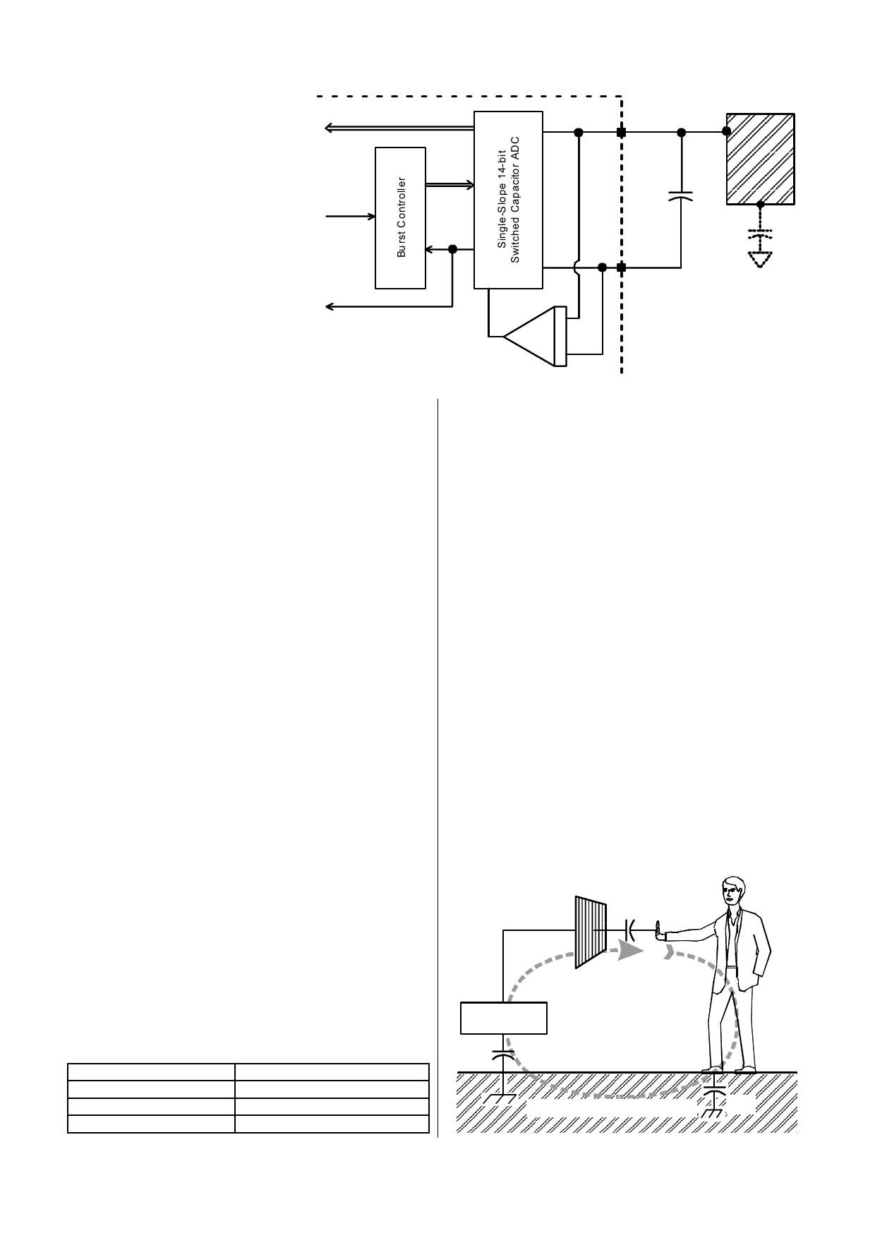
field flows. By implication it requires that
the signal ground and the target object
must both be coupled together in some
manner for a capacitive sensor to
operate properly. Note that there is no
need to provide actual hardwired ground
connections; capacitive coupling to
ground (Cx1) is always sufficient, even if
the coupling might seem very tenuous.
For example, powering the sensor via an
isolated transformer will provide ample
ground coupling, since there is
capacitance between the windings
and/or the transformer core, and from
the power wiring itself directly to 'local
earth'. Even when battery powered, just
the physical size of the PCB and the
object into which the electronics is
embedded will generally be enough to
couple a few picofarads back to local
earth.
R esul t
Start
Figure 1-3 Internal Switching & Timing
SNS2
E LEC TRO DE
Do ne
Cs
Cx
SNS1
C harg e
Amp
1.3.3 VIRTUAL CAPACITIVE GROUNDS
When detecting human contact (e.g. a fingertip), grounding of
the person is never required. The human body naturally has
several hundred picofarads of ‘free space’ capacitance to the
local environment (Cx3 in Figure 1-3), which is more than two
orders of magnitude greater than that required to create a
return path to the QT110 via earth. The QT110's PCB however
can be physically quite small, so there may be little ‘free space’
coupling (Cx1 in Figure 1-3) between it and the environment to
complete the return path. If the QT110 circuit ground cannot be
earth grounded by wire, for example via the supply
connections, then a ‘virtual capacitive ground’ may be required
to increase return coupling.
A ‘virtual capacitive ground’ can be created by connecting the
QT110’s own circuit ground to:
- A nearby piece of metal or metallized housing;
- A floating conductive ground plane;
- Another electronic device (to which its might be connected
already).
Free-floating ground planes such as metal foils should
maximize exposed surface area in a flat plane if possible. A
square of metal foil will have little effect if it is rolled up or
crumpled into a ball. Virtual ground planes are more effective
and can be made smaller if they are physically bonded to other
surfaces, for example a wall or floor.
In some cases it may be desirable to increase sensitivity
further, for example when using the sensor with very thick
panels having a low dielectric constant.
Sensitivity can often be increased by using a bigger electrode,
reducing panel thickness, or altering panel composition to one
having a higher dielectric constant. Increasing electrode size
can have diminishing returns, as high values of Cx will reduce
sensor gain.
Increasing the electrode's surface area will not substantially
increase touch sensitivity if its diameter is already much larger
in surface area than the object being detected. Metal areas
near the electrode will reduce the field strength and increase
Cx loading and are to be avoided for maximal gain.
Ground planes around and under the electrode and its SNS
trace will cause high Cx loading and destroy gain. The possible
signal-to-noise ratio benefits of ground area are more than
negated by the decreased gain from the circuit, and so ground
areas around electrodes are discouraged. Keep ground,
power, and other signals traces away from the electrodes and
SNS wiring.
The value of Cs has a minimal effect on sensitivity with these
devices, but if the Cs value is too low there can be a sharp
drop-off in sensitivity.
1.3.4 SENSITIVITY
The QT110 can be set for one of 3 gain levels using option pin
5 (Table 1-1). If left open, the gain setting is high. The
sensitivity change is made by altering the numerical threshold
level required for a detection. It is also a function of other
things: electrode size, shape, and orientation, the composition
and aspect of the object to be sensed, the thickness and
composition of any overlaying panel material, and the degree
of ground coupling of both sensor and object are all influences.
Figure 1-5 Kirchoff's Current Law
CX2
Gain plots of the device are shown on page 9.
The Gain input should never be tied to anything other than
SNS1 or SNS2, or left unconnected (for high gain setting).
Se nse E le ctro de
Table 1-1 Gain Strap Options
Gain
High
Medium
Low
Tie Pin 5 to:
Leave open
Pin 6
Pin 7
SENSOR
CX 1
Su rro und ing enviro nm ent
CX3
LQ
3
QT110 R1.04/0405
Share Link: 