QT1101 View Datasheet(PDF) - Quantum Research Group
Part Name
Description
Manufacturer
QT1101 Datasheet PDF : 16 Pages
| |||
Oscillator Tolerance: While
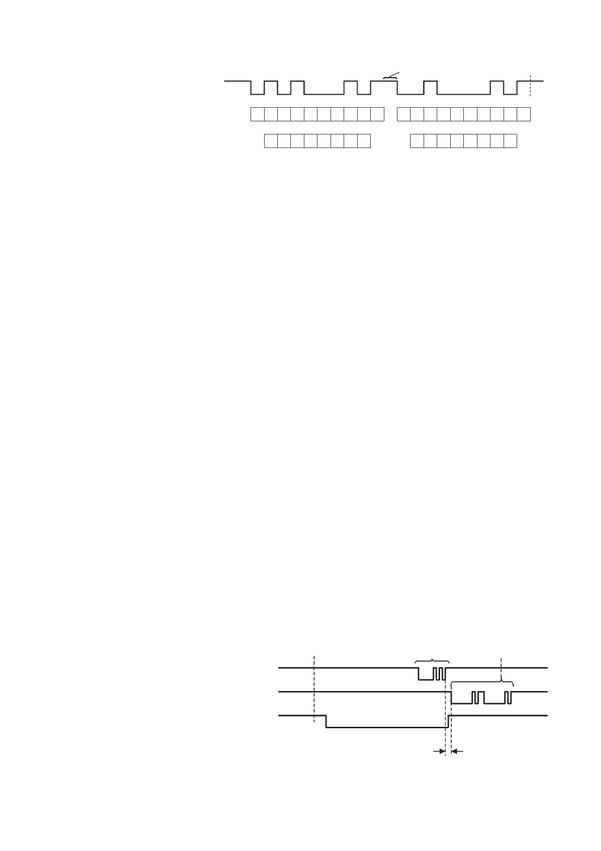
Figure 2.3 UART Response Pattern on 1W Pin
the auto baud rate detection
mechanism has a wide
floating
tolerance for oscillator error,
the QT’s oscillator should still
1W
floating
(from QT1101)
floating
not vary by more than ±20%
from the recommended value. Serial bits
S01234567S S01234567S
Beyond a 20% error,
communications at either the
lower or upper stated limits
Associated key #
012345* *
6 7 8 9UU * *
could fail. The oscillator
(Shown with keys 0, 2 and 7 detecting)
* Fixed bit values
frequency can be checked
U - Unused bits
with an oscilloscope by
probing the pulse width on
QT1101 will be at full speed, and hence will always respond
the SNS lines; these should ideally be 2.15µs in width each to ‘P’ requests.
at the beginning of a burst with the recommended
spread-spectrum circuit, or 2µs wide if no spread-spectrum
circuit is used.
Note that when sleeping in LP mode, there are by definition
no keys active, so there should not be a reason for the host
to send the ‘P’ query command in the first place.
Host Request Byte: The host requests the key state from
the QT1101 by sending an ASCII "P" character (ASCII
decimal code 80, hex 0x50) over the 1W line. The character
is formatted according to conventional RS-232:
Three strategies are available to the host to ensure that LP
mode operates correctly:
# /CHANGE used. The host monitors /CHANGE, and only
8 data bits
no parity
1 stop bit
baud rate: 8,000 - 38,400
sends a ‘P’ request when it is low. The part is awake by
definition when /CHANGE is low. If /CHANGE is high,
key states are known to be unchanged since the last
reply received from the QT1101, and so additional ‘P’
requests are not needed. Before triggering LP mode the
Figure 2.2 shows the bit pattern of the host request byte
host should wait for /CHANGE to go high after all keys
(‘P’). The first bit labeled ‘S’ is the start bit, the last ‘S’ is the
have become inactive.
stop bit. This bit pattern should never be changed. The
QT1101 will respond at the same baud rate as the received
‘P’ character.
# DETECT used. The host monitors DETECT, and if it is
active (i.e. the part is awake) it polls the device regularly
to obtain key status. When DETECT is inactive (the part
After sending the ‘P’ character the host must immediately
may be sleeping) no requests are sent because it is
float the 1W signal to prevent a drive conflict between the
known that no keys are active. Before triggering LP
host and the QT1101 (see Figure 2.1). The delay from the
mode the host should wait for DETECT to become
received stop bit to the QT1101 driving the 1W pin is in the
inactive, and then send one additional 'P' request to
range 1-3 bit periods, so the host should float the pin within
ensure /CHANGE is also made inactive.
one bit period to prevent a drive conflict.
# Neither /CHANGE nor DETECT used. The host polls
Data Reply: Before sending a reply, the QT1101 returns the
the device regularly to obtain key status, with a timeout
/CHANGE signal to its inactive (float-high) state.
in operation when awaiting the reply to each ‘P’ request.
The QT1101 then replies by sending two eight-bit characters
to the host over the 1W line using the same baud rate as the
request. With no keys pressed, both repl y bytes are ASCII
‘@’ (0x40) characters; any keys that are pressed at the time
of the reply result in their associated bits being set in the
reply. Figure 2.3 shows the reply bytes when keys 0, 2 and 7
Not receiving a reply within the timeout period only
occurs when the part is sleeping, and hence when no
keys are active. Before triggering LP mode the host
should wait for all keys to become inactive and then
send an additional 'P' request to the QT1101 to ensure
/CHANGE is also inactive.
are pressed - 0x45, 0x42, and the associations between
keys and bits in the reply.
The QT1101 floats the 1W pin again after establishing the
level of the stop bit.
2.11.3 2W Operation
1W operation, as described above, requires that the host
float the 1W line while awaiting a reply from the QT1101; this
is not always possible.
2.11.2 LP Mode Effects on 1W
The use of low power (LP) mode
presents some additional 1W timing
requirements. In LP mode (Section
2.5), the QT1101 will only respond to
a request from the host when it is
making one of its infrequent checks
for a key press. Hence, in that
condition most requests from the host
to the QT1101 will be ignored, since
the QT1101 will be sleeping and
unresponsive. However, if either
/CHANGE or DETECT are active the
RX
(from host)
1W
(from QT1101)
/CHANGE
Figure 2.4 2W Operation
key state
change
request
from host
(1 byte)
floating
floating
driven reply
from QT1101
(2 bytes)
floating
floating
1 ~ 3 bit periods
Lq
8
QT1101 R4.06/0806
Share Link: 