QT1103-ISG View Datasheet(PDF) - Quantum Research Group
Part Name
Description
Manufacturer
QT1103-ISG Datasheet PDF : 22 Pages
| |||
After sending the ‘P’ character
the host must immediately
float the 1W signal to prevent
a drive conflict between the
host and the QT1103 (see
Figure 2.6). The delay from
the received stop bit to the
QT1103 driving the 1W pin is
in the range 1-3 bit periods,
so the host should float the
pin within one bit period to
prevent a drive conflict.
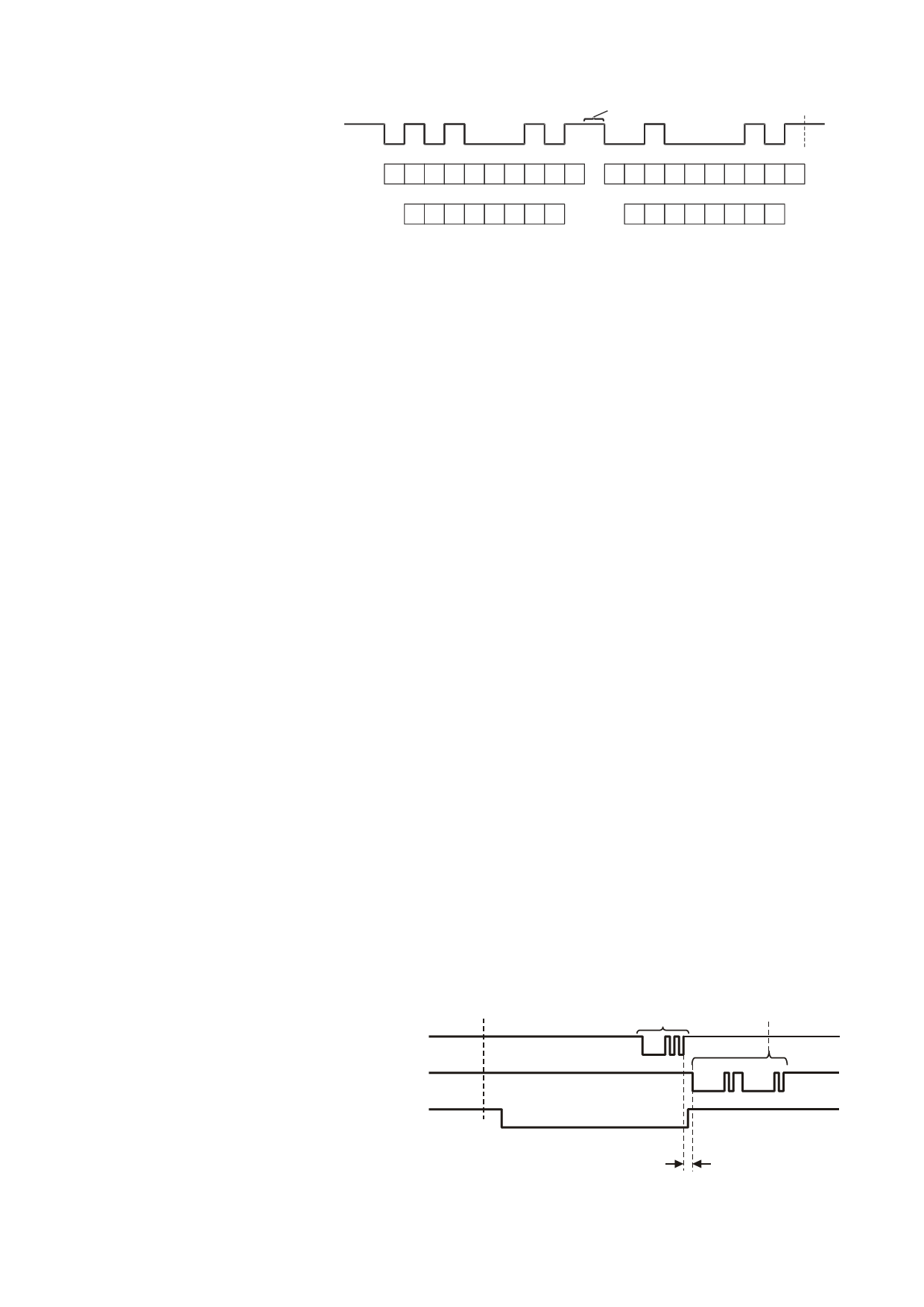
Figure 2.8 UART Response Pattern on 1W Pin
1W
floating
(from QT1103)
Serial bits
S01234567S
floating
floating
S01234567S
Associated key #
012345* *
6 7 8 9UU * *
(shown with keys 0, 2 and 7 detecting)
* Fixed bit values
U - Unused bits
Data Reply: Before sending a
reply, the QT1103 returns the /CHANGE signal to its inactive
(float-high) state.
The QT1103 then replies by sending two eight-bit characters
to the host over the 1W line using the same baud rate as the
request. With no keys pressed, both reply bytes are ASCII
‘@’ (0x40) characters; any keys that are pressed at the time
of the reply result in their associated bits being set in the
reply. Figure 2.8 shows the reply bytes when keys 0, 2 and 7
are pressed - 0x45, 0x42, and the associations between keys
and bits in the reply.
The QT1103 floats the 1W pin again after establishing the
level of the stop bit.
2.11.3 LP Mode Effects on 1W
The use of low power (LP) mode presents some additional
1W timing requirements. In LP mode (Section 2.5), the
QT1103 will only respond to a request from the host when it
is making one of its infrequent checks for a key press. Hence,
in that condition most requests from the host to the QT1103
will be ignored, since the QT1103 will be sleeping and
unresponsive. However, if either /CHANGE or DETECT are
active the QT1103 will be at full speed, and hence will always
respond to ‘P’ requests.
Note that when sleeping in LP mode, there are by definition
no keys active, so there should not be a reason for the host
to send the ‘P’ query command in the first place.
• Neither /CHANGE nor DETECT used. The host polls
the device regularly to obtain key status, with a
timeout in operation when awaiting the reply to each
‘P’ request. Not receiving a reply within the timeout
period only occurs when the part is sleeping, and
hence when no keys are active. Before triggering LP
mode the host should wait for all keys to become
inactive and then send an additional 'P' request to the
QT1103 to ensure /CHANGE is also inactive.
2.11.4 2W Operation
1W operation, as described in Section 2.11.3, requires that
the host float the 1W line while awaiting a reply from the
QT1103; this is not always possible.
To solve this problem, the QT1103 can also receive the ‘P’
character from the host on its ‘Rx’ pin separately from the 1W
pin (Figure 2.9). The host need not float the Rx line since the
QT1103 will never try to drive it.
Following a ‘P’ on Rx, the QT1103 will send the same
response pattern (Figure 2.8) over the 1W line as in pure 1W
mode.
All other comments and timings given for 1W operation are
applicable for 2W operation. LP operation is the same for 2W
mode as for 1W.
If the Rx pin is not used, it must be tied to Vdd.
Three strategies are available to the host to ensure that LP
mode operates correctly:
3 Design Notes
• /CHANGE used. The host monitors /CHANGE, and
only sends a ‘P’ request when it is low. The part is
awake by definition when /CHANGE is low. If
/CHANGE is high, key states are known to be
unchanged since the last reply received from the
QT1103, and so additional ‘P’ requests are not
needed. Before triggering LP mode the host should
3.1 Oscillator Frequency
The QT1103’s internal oscillator runs from an external
network connected to the OSC and SS pins as shown in
Figures 1.1 and 1.2. The charts in these figures show the
recommended values to use depending on nominal operating
voltage and spread spectrum mode.
wait for /CHANGE to go high after all keys have
become inactive.
If spread spectrum mode is not used, only resistor Rb1
should be used, the Css capacitor eliminated, and the SS pin
• DETECT used. The host
pulled to Vss with a 100k resistor.
monitors DETECT, and if it is
active (i.e. the part is awake) it
Figure 2.9 2W Operation
polls the device regularly to
obtain key status. When
DETECT is inactive (the part
may be sleeping) no requests
key state
change
request
from host
(1 byte)
driven reply
(from QT1103)
(2 bytes)
are sent because it is known
that no keys are active. Before
RX
(from host)
triggering LP mode the host
should wait for DETECT to
become inactive, and then
1W
(from QT1103)
floating
floating
send one additional 'P' request
to ensure /CHANGE is also
/CHANGE floating
floating
made inactive.
1 ~ 3 bit periods
Lq
11
QT1103_3R0.03_0607
Share Link: 