RT100KP100A View Datasheet(PDF) - Microsemi Corporation
Part Name
Description
Manufacturer
RT100KP100A
Microsemi Corporation

RT100KP100A Datasheet PDF : 4 Pages
| |||
SCOTTSDALE DIVISION
RT100KP33A thru RT100KP400CA, e3
Preferred 100 kW Transient Voltage
Suppressor for AIRCRAFT POWER
BUS PROTECTION
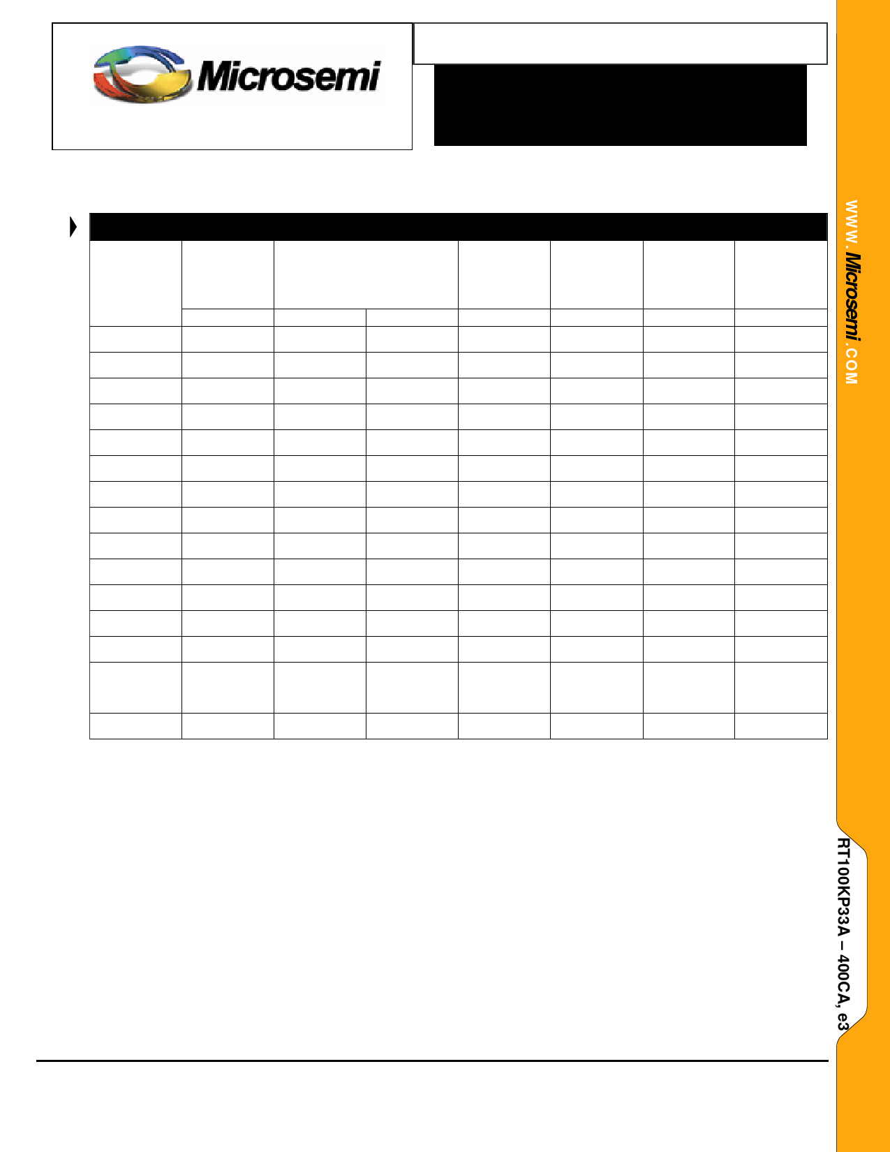
ELECTRICAL CHARACTERISTICS at 25ºC
Part
Number
(1) (4)
RT100KP33A
RT100KP36A
RT100KP40A
RT100KP43A
RT100KP45A
RT100KP48A
RT100KP51A
RT100KP54A
RT100KP58A
RT100KP60A
RT100KP64A
RT100KP70A
RT100KP75A
RT100KP78A
RT100KP85A
RT100KP90A
RT100KP100A
RT100KP110A
RT100KP120A
RT100KP130A
RT100KP150A
RT100KP160A
RT100KP170A
RT100KP180A
RT100KP200A
RT100KP220A
RT100KP250A
RT100KP260A
RT100KP280A
RT100KP300A
RT100KP350A
RT100KP400A
Rated
Stand-off
Voltage
VWM
VOLTS
33
36
40
43
45
48
51
54
58
60
64
70
75
78
85
90
100
110
120
130
150
160
170
180
200
220
250
260
280
300
350
400
Breakdown Voltage
V(BR) Volts
@ I(BR)
V(BR)
I(BR)
VOLTS
mA
36.7-40.6
50
40.0-44.2
50
44.4-49.1
20
47.8-52.8
10
50.0-55.3
5
53.3-58.9
5
56.7-62.7
5
60.0-66.3
5
64.4-71.2
5
66.7-73.7
5
71.1-78.6
5
77.8-86.0
5
83.3-92.1
5
86.7-95.8
5
94.4-104
5
100-111
5
111-123
5
122-135
5
133-147
5
144-159
5
167-185
5
178-197
5
189-209
5
200-221
5
222-245
5
245-271
5
278-308
5
289-320
5
311-345
5
333-369
5
389-431
5
444-492
5
Maximum
Clamping
@ IPP (2)
VC
VOLTS
58.6
61.8
68.6
71.0
73.0
77.7
82.8
87.5
94.0
97.3
104
114
122
126
137
146
162
178
193
209
243
259
275
291
322
356
403
419
451
483
564
644
Maximum
Reverse
Leakage
@ VWM
ID
μAmps
5000
5000
1500
500
150
150
50
25
15
15
10
10
10
10
10
10
10
10
10
10
10
10
10
10
10
10
10
10
10
10
10
10
Maximum
Peak Pulse
Current (3)
@6.4/69 µs
IPP
Amps
1825 *
1672 *
1518 *
1432 *
1365 *
1285 *
1205 *
1139 *
1066 *
1012 *
959 *
879
819
793
726
686
619
559
519
473
413
386
366
346
313
280
246
236
220
206
176
153
Maximum
V(BR)
temperature
Coefficient
αV(BR)
mV/oC
38
41
46
50
52
56
60
63
68
71
76
83
89
93
102
109
121
133
145
157
183
195
207
219
243
269
306
318
344
368
430
490
1. For bidirectional construction, indicate a CA suffix (instead of A) after the part number
2. Clamping voltage does not include any variable parasitic lead inductance effects observed during the 6.4 µs rise time due to lead length.
3. The Maximum Peak Pulse Current (IPP) shown represents the performance capabilities by design.
* Surge test screening is only performed up to 900 Amps (test equipment limitations).
4. Part numbers in bold italics are preferred devices.
Copyright © 2007
10-03-2007 Rev B
Microsemi
Scottsdale Division
8700 E. Thomas Rd. PO Box 1390, Scottsdale, AZ 85252 USA, (480) 941-6300, Fax: (480) 947-1503
Page 2
Share Link: