RT100KP100A View Datasheet(PDF) - Microsemi Corporation
Part Name
Description
Manufacturer
RT100KP100A
Microsemi Corporation

RT100KP100A Datasheet PDF : 4 Pages
| |||
SCOTTSDALE DIVISION
RT100KP33A thru RT100KP400CA, e3
Preferred 100 kW Transient Voltage
Suppressor for AIRCRAFT POWER
BUS PROTECTION
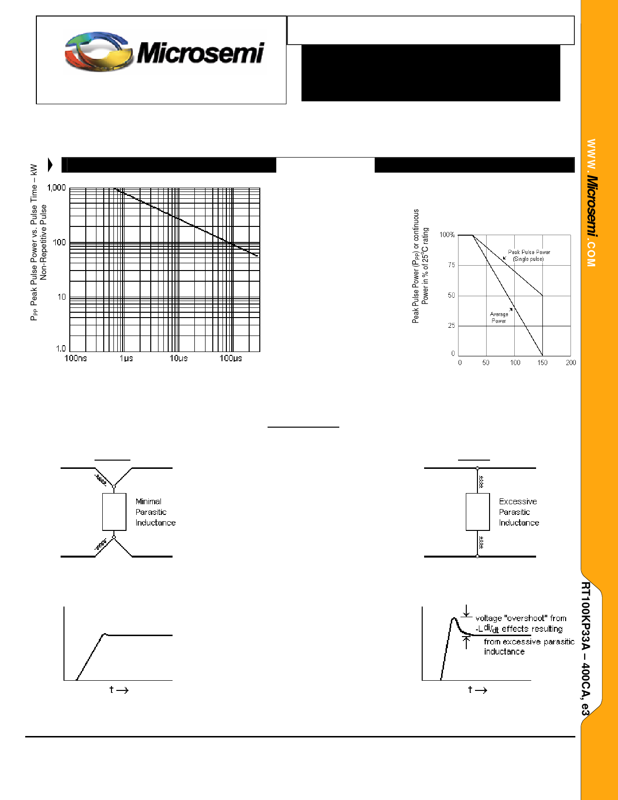
NOTE:GTRhAisPPHPSP versus
time graph allows the
designer to use these parts
over a broad power
spectrum using the
guidelines illustrated in
App Note 104 on
Microsemi’s website.
Aircraft transients are
described with exponential
decaying waveforms. For
suppression of square-
wave impulses, derate
power and current to 66%
of that for exponential
decay shown in Figure 1.
tp – Pulse Time – sec.
FIGURE 1
Peak Pulse Power vs. Pulse Time
To 50% of Exponentially Decaying Pulse
INSTALLATION
Correct
FIGURE 3
TVS devices used across power lines are
subject to relatively high magnitude surge
currents and are more prone to adverse
parasitic inductance effects in the mounting
leads. Minimizing the shunt path of the lead
inductance and their V= -Ldi/dt effects will
optimize the TVS effectiveness. Examples
of optimum installation and poor installation
are illustrated in figures 3 through figure 6.
Figure 3 illustrates minimal parasitic
inductance with attachment at end of device.
Inductive voltage drop is across input leads.
Virtually no “overshoot” voltage results as
illustrated with figure 4. The loss of
effectiveness in protection caused by
excessive parasitic inductance is illustrated
in figures 5 and 6. Also see MicroNote 111
for further information on “Parasitic Lead
Inductance in TVS”.
TL Lead Temperature oC
FIGURE 2
POWER DERATING
Wrong
FIGURE 5
FIGURE 4
FIGURE 6
Copyright © 2007
10-03-2007 Rev B
Microsemi
Scottsdale Division
8700 E. Thomas Rd. PO Box 1390, Scottsdale, AZ 85252 USA, (480) 941-6300, Fax: (480) 947-1503
Page 3
Share Link: