RT8015D View Datasheet(PDF) - Richtek Technology
Part Name
Description
Manufacturer
RT8015D Datasheet PDF : 14 Pages
| |||
Application Information
The basic RT8015D application circuit is shown in Typical
Application Circuit. External component selection is
determined by the maximum load current and begins with
the selection of the inductor value and operating frequency
followed by CIN and COUT.
Output Voltage Programming
The output voltage is set by an external resistive divider
according to the following equation :
VOUT
=
VREF
×
⎜⎝⎛1+
R1
R2
⎟⎠⎞
where VREF equals to 0.8V typical.
The resistive divider allows the FB pin to sense a fraction
of the output voltage as shown in Figure 1.
VOUT
R1
FB
RT8015D
R2
GND
Figure 1. Setting the Output Voltage
Soft-Start
The RT8015D contains an internal soft-start clamp that
gradually raises the clamp on the COMP pin. The full
current range becomes available on COMP after 2048
switching cycles as shown in Figure 2.
VIN
(2V/Div)
VOUT
(500mV/Div)
ILX
(1A/Div)
VIN = 5V, VOUT = 1.05V, IOUT = 2A
Time (1ms/Div)
Figure 2. Soft-Start
DS8015D-02 March 2011
RT8015D
Power-Good Output
The power good output is an open-drain output and requires
a pull-up resistor. When the output voltage is 12.5% above
or 12.5% below its set voltage, PGOOD will be pulled
low. It is held low until the output voltage returns to within
the allowed tolerances once more. In soft start, PGOOD
is actively held low and is allowed to transition high until
soft start finished over and the output voltage reaches
87.5% of its set voltage.
Operating Frequency
Selection of the operating frequency is a tradeoff between
efficiency and component size. High frequency operation
allows the use of smaller inductor and capacitor values.
Operation at lower frequency improves efficiency by
reducing internal gate charge and switching losses but
requires larger inductance and/or capacitance to maintain
low output ripple voltage.
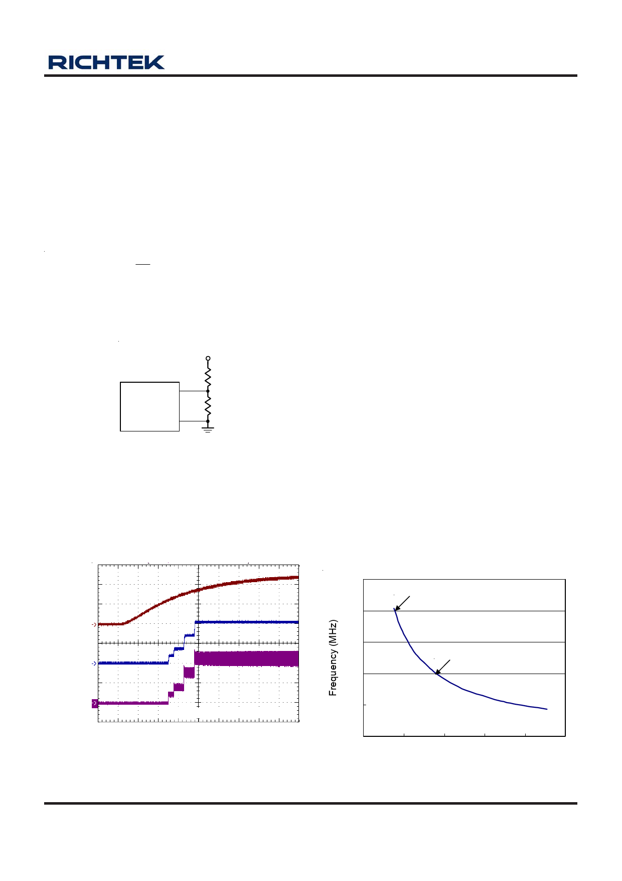
The operating frequency of the RT8015D is determined
by an external resistor that is connected between the RT
pin and ground. The value of the resistor sets the ramp
current that is used to charge and discharge an internal
timing capacitor within the oscillator. The RT resistor value
can be determined by examining the frequency vs. RT
curve. Although frequencies as high as 2MHz are possible,
the minimum on-time of the RT8015D imposes a minimum
limit on the operating duty cycle. The minimum on-time
is typically 110ns. Therefore, the minimum duty cycle is
equal to 100 x 110ns x f(Hz).
2.5
RT = 152k for 2MHz
2
1.5
RT = 330k for 1MHz
1
0.5
0
0
200
400
600
800
1000
ROSCC (kkٛΩ)
Figure 3
www.richtek.com
9
Share Link: 