S4S2RP View Datasheet(PDF) - Littelfuse, Inc
Part Name
Description
Manufacturer
S4S2RP Datasheet PDF : 10 Pages
| |||
Teccor® brand Thyristors
0.8 Amp Sensitive SCRs
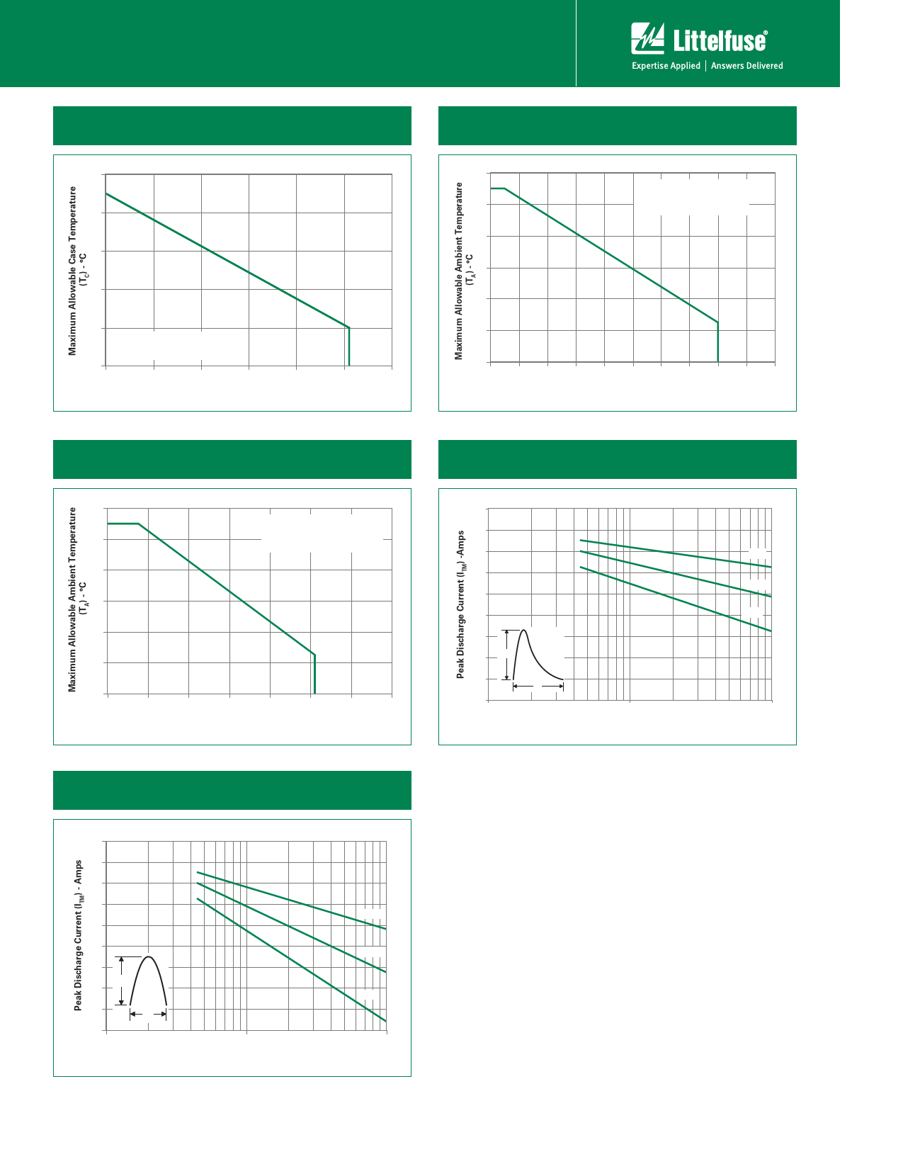
Figure 7: Maximum Allowable Case Temperature
vs. Average On-State Current
115
105
95
85
75
CURRENT WAVEFORM: Sinusoidal
LOAD: Resistive or Inductive
CONDUCTION ANGLE: 180┬░
65
0.0
0.1
0.2
0.3
0.4
0.5
0.6
Average On-State Current [IT(AVE)] - Amps
Figure 8: Maximum Allowable Ambient Temperature
vs. RMS On-State Current
120
CURRENT WAVEFORM: Sinusoidal
LOAD: Resistive or Inductive
100
CONDUCTION ANGLE: 180┬░
FREE AIR RATING
80
60
40
20
0
0.0 0.1 0.2 0.3 0.4 0.5 0.6 0.7 0.8 0.9 1.0
RMS On-State Current [IT(RMS)] - Amps
Figure 9: Maximum Allowable Ambient Temperature
vs. Average On-State Current
120
100
80
60
40
20
0
0.0
CURRENT WAVEFORM: Sinusoidal
LOAD: Resistive or Inductive
CONDUCTION ANGLE: 180┬░
FREE AIR RATING
0.1
0.2
0.3
0.4
0.5
0.6
0.7
Average On-State Current [IT(AVE)] - Amps
Figure 10: Peak Capacitor Discharge Current
180
160
140
120
100
80
60
40
#
20
0
1
10
"$
"$
!
"$
100
Figure 11: Peak Repetitive Sinusoidal Pulse Current
180
160
140
120
100
80
60
40
20
0
1
10
"#
"#
!
"#
100
EC103xx & SxSx Series
166
Revised: March 31, 2010 03:44 PM
┬®2010 Littelfuse, Inc
Speci’¼ücations are subject to change without notice.
Please refer to http://www.littelfuse.com for current information.
Share Link: 