SC1766 View Datasheet(PDF) - Semtech Corporation
Part Name
Description
Manufacturer
SC1766 Datasheet PDF : 11 Pages
| |||
BATTERY
CHARGE CONTROLLER
SC1766
Janaury 30, 1998
PRINCIPLES OF OPERATION (cont.)
-∆V detector of the SC1766 to work properly in test
mode, which is that the VBT voltage must be kept be-
tween approximately 2.8V to 3.3V, rather than 0.8V to
3.5V in NORMAL mode.
If the TEST mode function is to be utilized in produc-
tion test, it has to be well planned and included in the
circuit design phase to make the voltages of the VBT
pin and MODE pins extremely controllable. In addition,
an externally controllable TIMER pin can further reduce
the test time required for testing the SC1766 in TEST
mode.
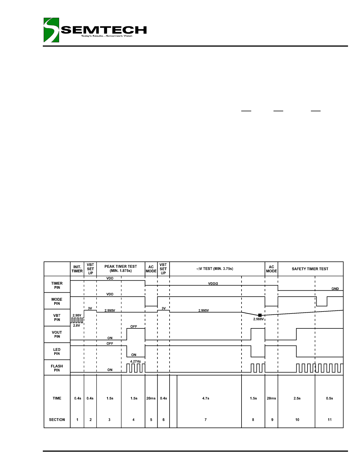
The figure below shows the timing diagram for exter-
nally controlled VBT, TIMER and MODE pin voltages
of a recommended SC1766 charge circuit production
test scheme, utilizing the TEST mode function. Output
waveforms of the VOUT and LED pins (and FLASH pin
for 14-pin version) of a properly functioning SC1766
are also shown in the figure. In time segments 4, 8 and
10, the VOUT pin should change from ON to OFF, the
LED pin from OFF to ON, and the FLASH pin from ON
to flashing output (approximately 4 Hz). For the rest of
the time, the VOUT pin should remain ON, the LED pin
OFF, and the FLASH pin ON. The LED indicators work
as follows:
LED
PIN
Fast Charge OFF
Trickle Charge ON
VBT Abnormal OFF
VOUT
PIN
ON
OFF
OFF
FLASH
PIN
ON
FLASH
OFF
The LED pin is used in conjunction with the VOUT pin
while the FLASH pin works alone.
Referring to the typical application circuit, the tempera-
ture limits beyond where the fast charge is prohibited
can be set by choosing values for resistors and the
thermistor of the thermistor divider according to the fol-
lowing formula:
R18 = 3.57 RT1 RT2 / (RT1-RT2)
R19 = 10 RT1 RT2 / (1.218RT1 - 11.2RT2)
RT1: Thermistor resistance at low temp. limit
RT2: Thermistor resistance at high temp. limit
Timing Diagram of the SC1766 in the Test Mode
© 1997 SEMTECH CORP.
652 MITCHELL ROAD NEWBURY PARK CA 91320
Share Link: 