SG6105ATP View Datasheet(PDF) - Fairchild Semiconductor
Part Name
Description
Manufacturer
SG6105ATP Datasheet PDF : 18 Pages
| |||
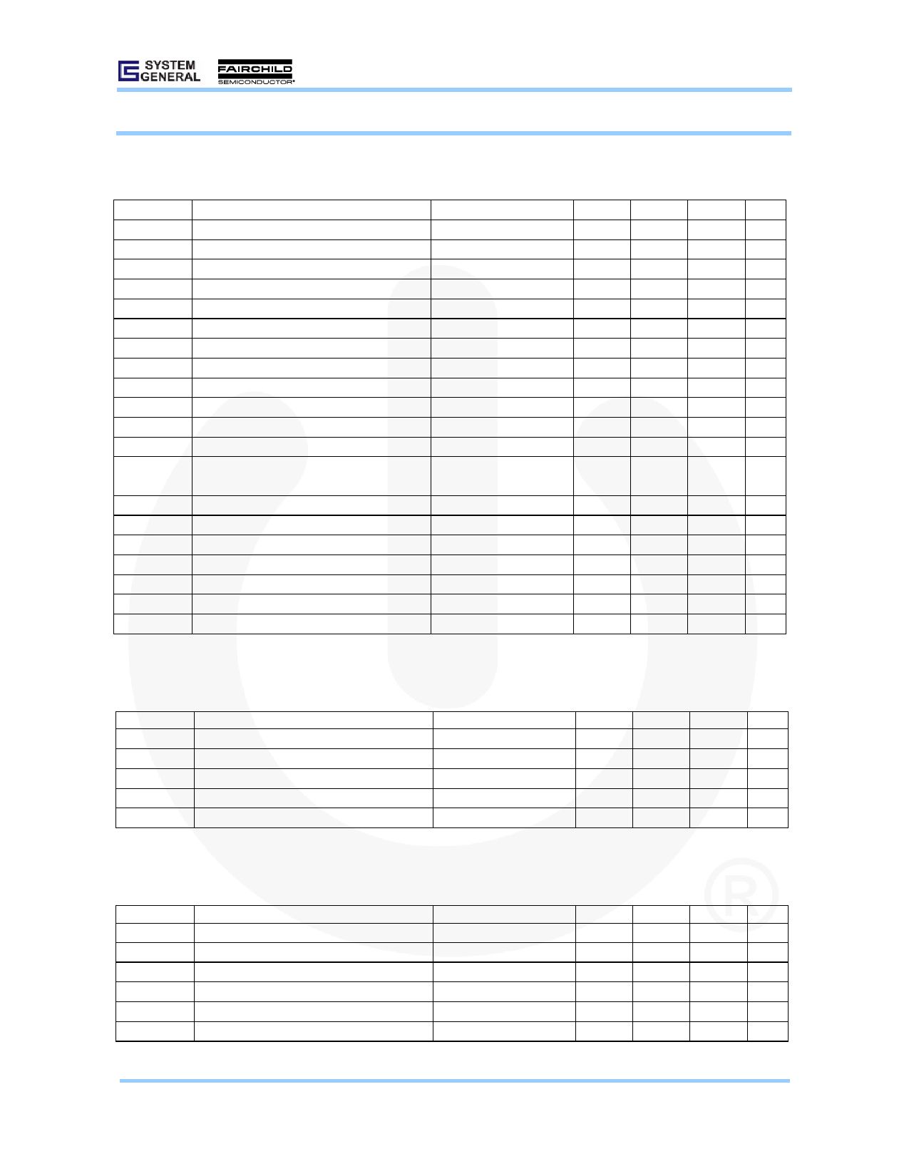
Power Supply Supervisor + Regulator + PWM
Product Specification
SG6105A
ELECTRICAL CHARACTERISTICS
Values are provided for 4.5V≦VCC≦5.5V, TA = -25°C~+85°C, RI = 75KΩ, unless noted.
Symbol
ICC
VOVP1
VOVP2
VOVP3
VUVP1
VUVP2
VUVP3
VUVS1
VUVS2
VUVS3
VOPP(*)
VOPPH
VX
Parameter
Test Condition
Total Supply Current
PG High
Over-Voltage Protection 3.3V
Over-Voltage Protection 5V
Over-Voltage Protection 12V
Under-Voltage Protection 3.3V
Under-Voltage Protection 5V
Under-Voltage Protection 12V
Under-Voltage Sense 3.3V for PG Low
Under-Voltage Sense 5V for PG Low
Under-Voltage Sense 12V for PG Low
Over-Power Protection (With TOPP Delay Time) VUVAC = 1.5V
Over-Power Protection (Without Delay Time)
Disable Under-Voltage / Over-Power
Protection Threshold
Min.
3.9
5.8
13.9
2.0
3.0
6.0
2.5
4.0
9.4
2.25
3.0
0.2
Typ.
5
4.1
6.1
14.5
2.6
3.6
7.2
2.8
4.3
10.1
2.32
3.2
0.3
VNVP
INVP
TOVP
TUVP
TUVS
TOPP
TNVP
Negative Voltage Protection: Voltage Level
Negative Voltage Protection: Source Current
Timing for Over-Voltage Protection
Timing for Under-Voltage Protection
Timing for Under-Voltage Sense for PG Low
Timing for Over-Power Protection
Timing for Negative Voltage Protection
2.0
2.1
63
67
0.37
0.70
0.80
2.40
0.37
1.20
5
7
3.3
7.0
Note *: VOPPS = (2/3) x VOPP + (1/3) x VUVAC.
Max.
10
4.3
6.5
14.9
2.8
3.9
8.0
3.0
4.5
10.4
2.39
3.4
0.4
2.2
71
1.35
3.75
1.88
9
10.2
Unit
mA
V
V
V
V
V
V
V
V
V
V
V
V
V
µA
ms
ms
ms
ms
ms
Shunt Regulator Section Current
Symbol
VREF
VDEV,
(**)
I
VDEV,
(**)
T
REGLI-FB(**)
IOUT-FB**
Parameter
Reference Voltage
Deviation of VREF Over FB Current
Deviation of VREF Over Temperature
Line Regulation
Output Sinking Current Capability
Note **: Not tested in production.
Test Condition
IFB = 0.5mA, TA = 25℃
IFB = 0.5mA to 10mA
4 ≦ VFB ≦ 15V
VFB = 2V
Min.
2.475
10
Typ.
2.500
10
1
Max.
2.525
20
30
Unit
V
mV
mV
mV/V
mA
Power-Good Section
Symbol Parameter
TPG
Timing for PG Delay
VUVAC
TR(**)
TF(**)
UVAC Voltage Sense for PG
Power -Good Output Rising Time
Power-Good Falling Time
VOL2
Power-Good Output Saturation Level
ION2
Power-Good Leakage Current Collector
Note **: Not tested in production.
© System General Corp.
Version 1.0.1 (IAO33.0072.B0)
Test Condition
Min.
RI = 75kΩ
200
0.68
CL = 100pF, Pull 2.2K to 5V
CL = 100pF, Pull 2.2K to 5V
IPG = 5mA
VPG = 5V
Typ.
300
0.70
1
300
Max.
400
0.72
3
500
0.5
1
Unit
ms
V
µs
ns
V
µA
-9-
www.sg.com.tw • www.fairchildsemi.com
September 25, 2007
Share Link: 