LC35W1000BM-10U View Datasheet(PDF) - SANYO -> Panasonic
Part Name
Description
Manufacturer
LC35W1000BM-10U Datasheet PDF : 9 Pages
| |||
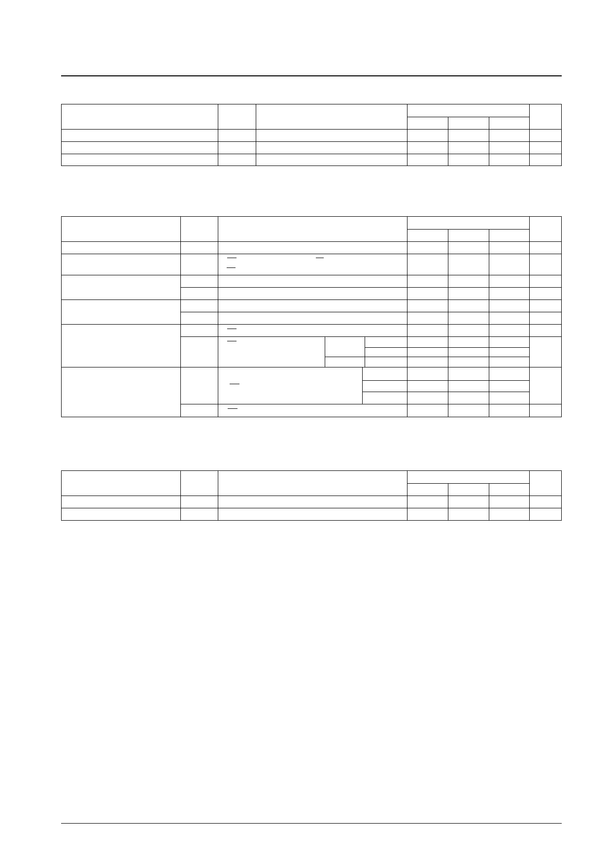
LC35W1000BM, BTS-70U/10U
DC Allowable Operating Range at Ta = –40 to +85°C
Parameter
Symbol
Supply volgate
VCC
High-level input voltage
VIH
Low-level input voltage
VIL
Note: * The minimum value is –3.0 V for pulse width under 50 ns.
Conditions
Ratings
Unit
min
typ
max
2.7
3.3
3.6
V
0.8VCC
–0.3*
VCC + 0.3
V
0.2VCC
V
DC Electrical Characteristics at Ta = –40 to +85°C, VCC = 2.7 to 3.6 V
Parameter
Symbol
Conditions
Input leakage current
I/O leakage current
Outpu high-level voltage
Outpu low-level voltage
Operating supply current
ILI
ILO
VOH1
VOH2
VOL1
VOL2
ICCA2
VIN = 0 to VCC
VCE1 = VIH or VCE2 = VIL or VOE = VIH or
VWE = VIL, VI/O = 0 to VCC
VOH1 = –2.0 mA
VOH2 = –100 µA
VOL1 = 2.0 mA
VOL2 = –100 µA
VCE1 = VIL, VCE2 = VIH, II/O = 0 mA, VIN = VIH or VIL
(CMOS inputs)
ICCA3
VCE1 = VIL, VCE2 = VIH,
II/O = 0 mA, VIN = VIH or VIL,
DUTY100%
min cycle
1 µs cycle
70 ns
100 ns
Standby mode supply current
(VCC – 0.2 V/0.2 V inputs)
(CMOS inputs)
ICCS1
ICCS2
VCE2 ≤ 0.2 V or
(VCE1 ≥ VCC – 0.2 V,
VCE2 ≥ VCC – 0.2 V)
VCE1 = VIH or VCE2 = VIL, VIN = 0 to VCC
Ta ≤ 85°C
Ta ≤ 70°C
Ta ≤ 25°C
Note: * Reference values when VCC = 3.0 V and Ta = 25°C.
min
–1.0
–1.0
VCC – 0.4
VCC – 0.1
2
Ratings
typ
0.1
Unit
max
+1.0
µA
+1.0
µA
V
V
0.4
V
0.1
V
1.2 mA
25
20 mA
20
10
µA
0.4 mA
I/O Capacitances at Ta = 25°C, f = 1 MHz
Parameter
Symbol
Conditions
Input capacitance
I/O capacitance
CIN
CI/O
VIN = 0 V
VI/O = 0 V
Note: These parameters are not measured for all devices, but are sampled values.
Ratings
Unit
min
typ
max
6
10
pF
6
10
pF
No. 6624-4/9
Share Link: 