SST25VF040B View Datasheet(PDF) - Silicon Storage Technology
Part Name
Description
Manufacturer
SST25VF040B Datasheet PDF : 33 Pages
| |||
Data Sheet
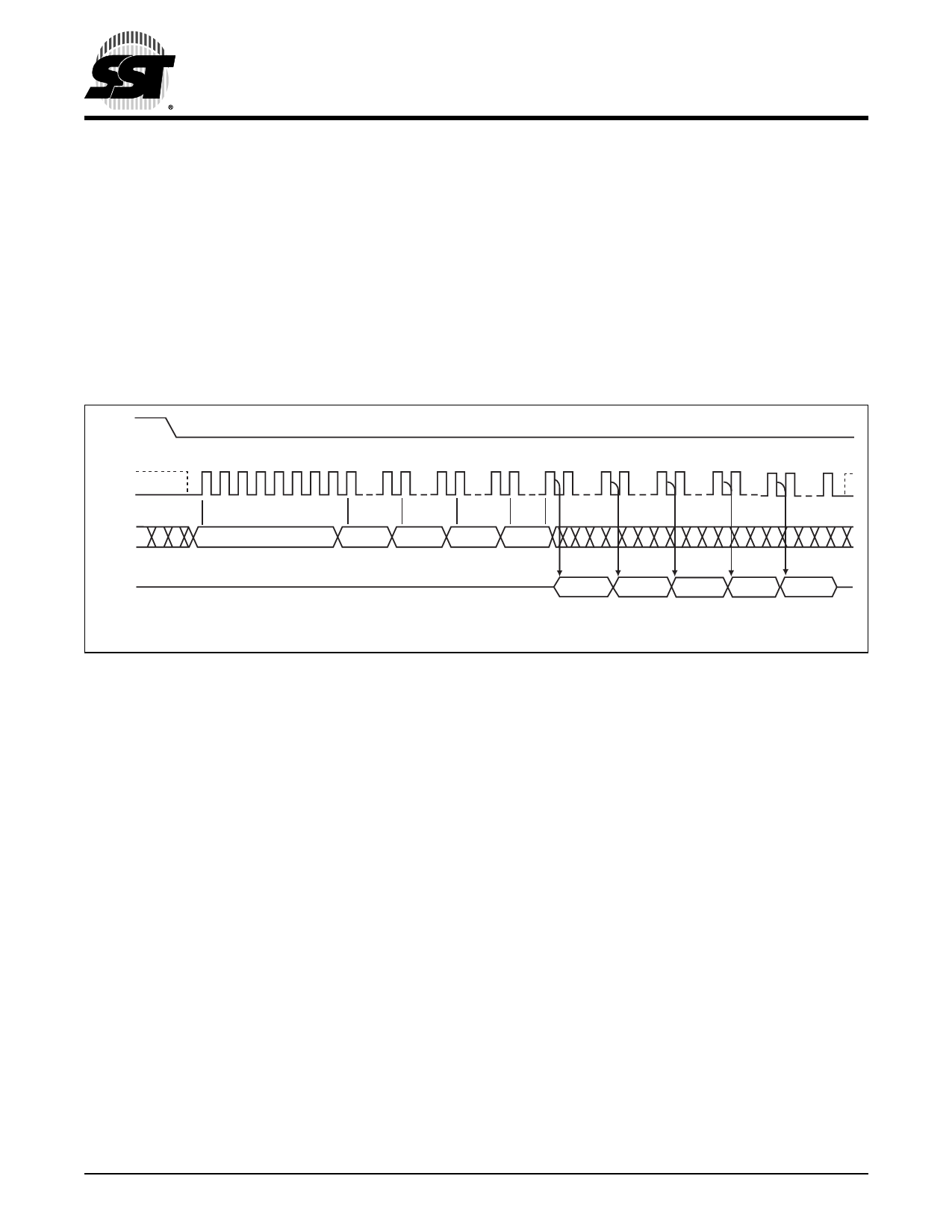
High-Speed-Read (50/80 MHz)
The High-Speed-Read instruction supporting up to 50 MHz
(for SST25VF040B-50-xx-xxF) or 80 MHz (for
SST25VF040B-80-xx-xxE) Read is initiated by executing
an 8-bit command, 0BH, followed by address bits [A23-A0]
and a dummy byte. CE# must remain active low for the
duration of the High-Speed-Read cycle. See Figure 6 for
the High-Speed-Read sequence.
Following a dummy cycle, the High-Speed-Read instruc-
tion outputs the data starting from the specified address
location. The data output stream is continuous through all
4 Mbit SPI Serial Flash
SST25VF040B
addresses until terminated by a low to high transition on
CE#. The internal address pointer will automatically incre-
ment until the highest memory address is reached. Once
the highest memory address is reached, the address
pointer will automatically increment to the beginning (wrap-
around) of the address space. Once the data from address
location 7FFFFH has been read, the next output will be
from address location 00000H.
CE#
MODE 3 0 1 2 3 4 5 6 7 8 15 16 23 24 31 32 39 40 47 48 55 56 63 64 71 72 80
SCK MODE 0
SI
0B
ADD. ADD. ADD.
X
MSB
MSB
SO
HIGH IMPEDANCE
N
DOUT
N+1
DOUT
N+2
DOUT
N+3
DOUT
N+4
DOUT
Note: X = Dummy Byte: 8 Clocks Input Dummy Cycle (VIL or VIH)
MSB
1295 HSRdSeq.0
FIGURE 6: High-Speed-Read Sequence
©2009 Silicon Storage Technology, Inc.
10
S71295-05-000
10/09
Share Link: 