ST7232A View Datasheet(PDF) - STMicroelectronics
Part Name
Description
Manufacturer
ST7232A Datasheet PDF : 157 Pages
| |||
ST7232A
6.2 MULTI-OSCILLATOR (MO)
The main clock of the ST7 can be generated by
two different source types coming from the multi-
oscillator block:
■ an external source
■ 4 crystal or ceramic resonator oscillators
Each oscillator is optimized for a given frequency
range in terms of consumption and is selectable
through the option byte. The associated hardware
configurations are shown in Table 5. Refer to the
electrical characteristics section for more details.
Caution: The OSC1 and/or OSC2 pins must not
be left unconnected. For the purposes of Failure
Mode and Effect Analysis, it should be noted that if
the OSC1 and/or OSC2 pins are left unconnected,
the ST7 main oscillator may start and, in this con-
figuration, could generate an fOSC clock frequency
in excess of the allowed maximum (>16MHz.),
putting the ST7 in an unsafe/undefined state. The
product behaviour must therefore be considered
undefined when the OSC pins are left unconnect-
ed.
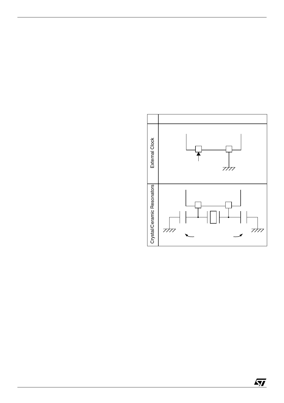
External Clock Source
In this external clock mode, a clock signal (square,
sinus or triangle) with ~50% duty cycle has to drive
the OSC1 pin while the OSC2 pin is tied to ground.
Crystal/Ceramic Oscillators
This family of oscillators has the advantage of pro-
ducing a very accurate rate on the main clock of
the ST7. The selection within a list of 4 oscillators
with different frequency ranges has to be done by
option byte in order to reduce consumption (refer
to Section 14.1 on page 145 for more details on
the frequency ranges). In this mode of the multi-
oscillator, the resonator and the load capacitors
have to be placed as close as possible to the oscil-
lator pins in order to minimize output distortion and
start-up stabilization time. The loading capaci-
tance values must be adjusted according to the
selected oscillator.
These oscillators are not stopped during the
RESET phase to avoid losing time in the oscillator
start-up phase.
Table 5. ST7 Clock Sources
Hardware Configuration
ST7
OSC1
OSC2
EXTERNAL
SOURCE
ST7
OSC1
OSC2
CL1
CL2
LOAD
CAPACITORS
24/157
1
Share Link: 