ST7265X View Datasheet(PDF) - STMicroelectronics
Part Name
Description
Manufacturer
ST7265X Datasheet PDF : 166 Pages
| |||
ST7265x
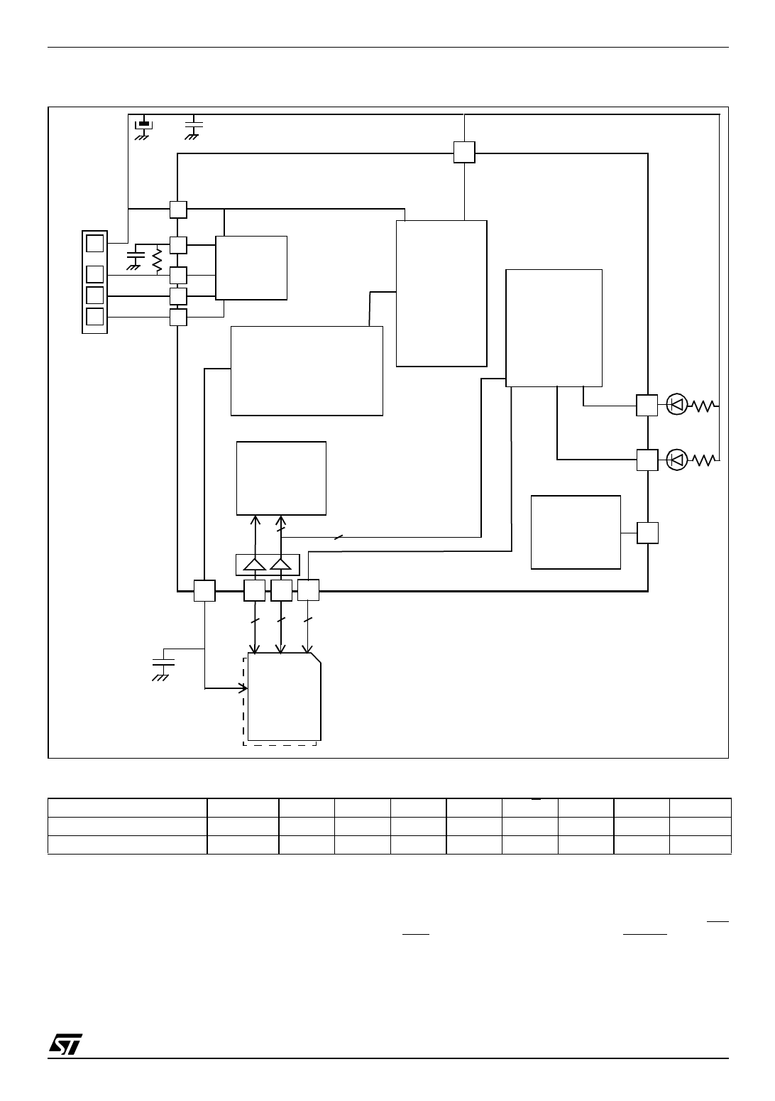
Figure 8. Smartmedia Card Writer Or Flash Drive Application Example
4.7µF
100nF
VDD
USBVDD
=4.0-5.5V
USBVDD
USB Port
5V
100nF
DP
1.5KΩ USB
VCC
DP
DM
GND
DM
USB
GND
USB
REGULATOR
POWER
MANAGEMENT
(4)
I/O
LOGIC
LED1
DTC
5
1
level translator
VDDF
PB PA PE
862
100nF
I/O CTRL
0~7
VDD
UP TO 2
SMARTMEDIA
CARDS
FLASH
LED2
VPP
12V for
Flash prog.
(connect to
GND if
not used)
Table 2. SmartMedia Interface Pin Assignment
SmartMedia Pin
ST72F65 pin
ST7 / DTC (1)
I/O0~7
PB0-7
DTC
CLE
PA0
DTC
WE
PA1
DTC
(1): This line shows if the ST72F65 pin is controlled by the
ST7 core or the DTC.
(2): These lines are not controlled by the DTC but by the
user software running on the ST7 core. The ST72F65 pin
choice is at customer discretion. The pins shown here are
only shown as an example.
(3): When a single card is to be handled, PA7 is free for
other functions. When 2 Smartmedia are to be handled,
pins from both cards should be tied together (i.e. CLE1
ALE
PA2
DTC
RE
PA3
DTC
R/B
PA4
DTC
WP(2)
PA7
ST7
CE1(2)
PE1
ST7
CE2(2)(3)
PE0
ST7
with CLE2...) except for the CE pins. CE pin from card 1
should be connected to PA6 and CE pin from card 2
should be connect to PA7. Selection of the operating card
is done by ST7 software.
(4) As this is a single power supply application, the US-
BEN function in not needed. Thus PF4/USBEN pin can be
used as a normal I/O by configuring it as such by the op-
tion byte.
15/166
1
Share Link: 