LXM1641-02(1999) View Datasheet(PDF) - Microsemi Corporation
Part Name
Description
Manufacturer
LXM1641-02 Datasheet PDF : 11 Pages
| |||
RangeMAXTM
PRODUCT DATABOOK 1996/1997
LXM1641-01/-02/-03
DIGITAL DIMMING QUAD LAMP CCFL INVERTER MODULE
PRELIMINARY DATA SHEET
1000:1 DIMMING APPLICATION
The following application defines techniques capable of deliver-
ing dimming ranges in the 250:1 and 1000:1 range. As is widely
understood, these techniques will provide general capabilities and actual
system performance will vary with panel design, CCFTs, ambient tem-
perature and a number of other variables outside the control of the
inverter. These methods can be used in conjunction with other tech-
niques such as lamp heating and matching.
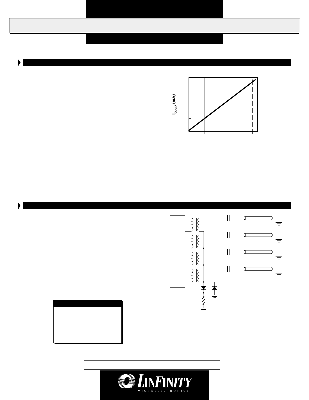
Wide ratio (1000:1) dimming can be accomplished using the Linfinity
inverter in two ways:
1) By varying the input voltage on the brightness pin as
indicated in Figure 12. Caution must be exercised when
applying negative voltage to the brightness control input.
Applying more than -300mV to any inverter input will cause
inverter malfunction (see Absolute Maximum Ratings).
2) By making a resistor value change on the module. If this
option is preferrable, please contact the factory for applica-
tion assistance.
Both methods discussed will provide a lower duty cycle
operation than is necessary in a 100:1 dimming application.
Careful consideration should be made with regards to display quality
7
0.7
.14
.070
-100mV
0V
V (V)
BRT ADJ
2.5V
FIGURE 12 — Average Lamp Current vs. V Voltage
BRITE
(per Lamp)
at these dimming levels. At very low brightness levels, even very small
amounts of noise on the VBRITE line can cause flicker on the display, so
special care must be given to grounding, filtering and shielding the
inverter from the digital logic and clock.
FAILSAFE FEATURE FOR MULTIPLE LAMP OPERATIONS
Our multi-output inverters are designed to keep your application
operating at near normal brightness in the event that a lamp fails.
This allows the display to remain "on-line" until lamp replacement
is convenient.
Linfinity "parallels" the lamps so that if any lamps break, most
of the current is added to the remaining good lamps. CCFLs will
respond with more brightness for a period of time. Operating time
in this mode will be a function of the lamps age but should be
typically in the order of hundreds of hours.
This operating characteristic can provide adequate display
performance for a limited, but useful period of time. Shortening
of the lamp life in this mode is typically not a concern as it is
recommended that all lamps in a display be replaced at the same
time.
IS
RangeMAX INVERTERS
Also available in Single
Output LXM1611-01,
LXM1612-xx-xx and Dual
Output LXM1621-xx versions
for multiple lamp applications.
Lamps
FIGURE 13 — Quad Output Stage
Copyright © 1999
Rev. 0.7 12/99
RangeMAX and Direct Drive are trademarks of Linfinity Microelectronics Inc.
PRELIMINARY DATA - Information contained in this document is pre-production data, and is proprietary to LinFinity. It may
not modified in any way without the express written consent of LinFinity. Product referred to herein is offered in sample form
only, and Linfinity reserves the right to change or discontinue this proposed product at any time.
11
Share Link: 