LXM1641-02(1999) View Datasheet(PDF) - Microsemi Corporation
Part Name
Description
Manufacturer
LXM1641-02 Datasheet PDF : 11 Pages
| |||
RangeMAXTM
PRODUCT DATABOOK 1996/1997
LXM1641-01/-02/-03
DIGITAL DIMMING QUAD LAMP CCFL INVERTER MODULE
PRELIMINARY DATA SHEET
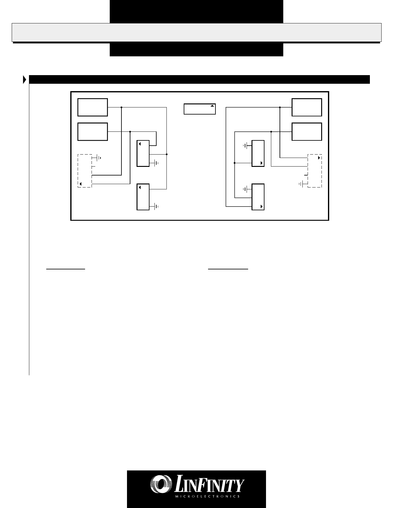
CONNECTOR SCHEMATIC
Inverter VHI2
Output 2
CN1
8
1
VHI4 Inverter
Output 4
Inverter VHI1
Output 1
4
3 N.C.
2
1
CN2
1
2
3
CN4
1
2
CN5
2
1
CN6
3
2
1
CN7
VHI3 Inverter
Output 3
1
2
N.C. 3
4
CN3
FIGURE 2 — LXM1641-01 Connector Schematic
Note: CN2 and CN3 (shown with dashed lines) are located on the opposite side of the PCB from CN1, CN4,
CN5, CN6, and CN7. Their pin numbers are shown as viewed looking through the printed circuit board.
Connectors:
CN1 = MOLEX 53261-0890
CN2, CN3 = JST SM04(4.0)B-BHS-1-TB
CN4, CN7 = JST SM03(4.0)B-BHS-1-TB
CN5, CN6 = JST SM02(8.0)B-BHS-1-TB
Mates With:
Pins: 50079-8100*, Housing: 51021-0800
* Loose (-8000, Chain) Recommended #26 AWG wiring
JST BHR-04VS-1
JST BHR-03VS-1
JST BHR-03VS-1
Connection Rules
1. Always install FOUR (4) lamps. Operating with fewer lamps may overdrive lamp current at maximum brightness settings.
2. Verify lamp wiring before connecting lamps to the inverter module. Connecting multiple lamps to one of the four inverter output
circuits will result in reduced brightness. The LXM1641-01 module connectors are wired per industry standard. The lamp hot wires
(high voltage wires) are always on pin 1 or 2, and the cold wire (low voltage wire) is always on pin 3 or 4.
Copyright © 1999
Rev. 0.7 12/99
5
Share Link: 