TB2110FN View Datasheet(PDF) - Toshiba
Part Name
Description
Manufacturer
TB2110FN Datasheet PDF : 19 Pages
| |||
TB2110FN
○ Programmable counter
The programmable counter section consists of 1 / 4 + 1 / 2 prescalers, 2 modulus prescaler, and 4bit + 12bit
programmable binary counters.
1. Setting the programmable counter section
The programmable counter need to be set for the divisor (16 bits) and the dividing mode (2 bits).
(1) Setting the dividing mode
Use the FM and mode bit to choose the input setting and the dividing mode (pulse swallow mode or direct
dividing mode). Four mode are available as listed below. Choose the desired one according to the
frequency bands used.
Mode FM Mode
Dividing Mode
AM
0
SW
0
FM
1
TV
1
0 Direct dividing mode
1 Pulse swallow mode
0 1 / 4 + pulse swallow mode
1 1 / 8 + pulse swallow mode
Typical
Receiving Band
LW, MW
SW
FM
TV
Input Frequency
Range
0.5~10MHz
3~40MHz
40~150MHz
50~250MHz
Input
Pin
AMIN
FMIN
(Note) ‘n’ denotes the set value.
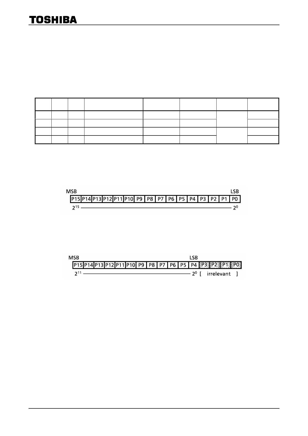
(2) Setting the divisor
To determine the programmable counter’s divisor, set binary data to the P0~P15 bits.
· For the pulse swallow mode (16 bits, SW, FM, and TV band)
Divisor
n
n
4・n
8・n
Range of divisor set (pulse swallow mode) n = 210H~FFFFH (528~65535)
(Note) The actual divisor is 4 times the programmed number for the 1 / 4 + pulse swallow mode, and
8 times the programmed number for the 1 / 8 + pulse swallow mode.
· Direct divide method (12 bits)
Range of divisor set (direct divide mode) n = 10H~FFFH (16~4095)
(Note) In the direct divide method, the data in P0~P3 becomes irrelevant and the P4 port becomes
the LSB.
9
2002-10-30
Share Link: 