TB2922HQ View Datasheet(PDF) - Toshiba
Part Name
Description
Manufacturer
TB2922HQ Datasheet PDF : 15 Pages
| |||
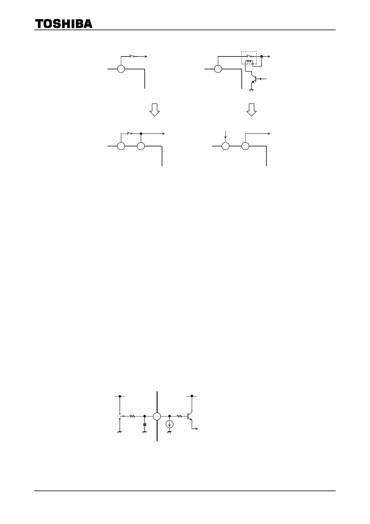
Large current capacity switch
Battery
VCC
VCC
– Conventional Method –
TB2922HQ
Relay
Battery
From
microcomputer
Small current capacity switch From microcomputer
Battery
Stand-By VCC
Stand-By VCC
– Standby Switch Method –
Battery
Figure 3
3. Muting Function (pin 6)
Audio muting function is enabled when pin 6 is Low. When the time constant of the muting function is
determined by R1 and C4, it should take into account the pop noise. The pop noise, which is generated when
the power or muting function is turned ON/OFF, will vary according to the time constant. (Refer to
Figure4)
The pin 6 is designed to operate off 5 V so that the outside pull-up resistor R1 is determined on the basic of
this value:
ex) When control voltage is changed in to 6 V from 5 V.
6 V/5 V × 47 k = 56 k
Additionally, as the VCC is rapidly falling, the IC internal low voltage muting operates to eliminate the
large pop noise basically.
The low voltage muting circuit pull 200 μA current into the IC so that the effect of the internal low
voltage muting does not become enough if the R1 is too small value.
To obtain enough operation of the internal low voltage muting, a series resistor, R1 at pin 6 should be
47 kΩ or more.
5V
6
R1
C4
1 kΩ
Mute ON/OFF
control
Figure 4 Muting Function
4
2007-02-20
Share Link: 