TC646 View Datasheet(PDF) - Microchip Technology
Part Name
Description
Manufacturer
TC646 Datasheet PDF : 28 Pages
| |||
TC646
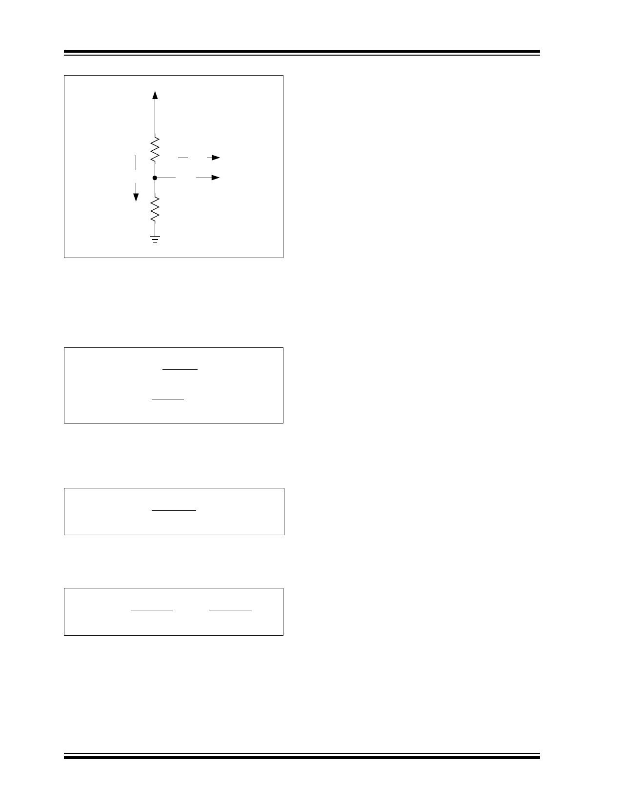
VDD
R1
IIN
IDIV
VAS
R2
GND
FIGURE 5-3:
VAS CIRCUIT
Per Section 1.0, “Electrical Characteristics”, the leak-
age current at the VAS pin is no more than 1 µA. It is
conservative to design for a divider current, IDIV, of
100 µA. If VDD = 5.0V then…
EQUATION
5.0V
IDIV = 1e–4A =
, therefore
R1 + R2
R1 + R2 =
5.0V
1e–4A
= 50,000Ω = 50kΩ
We can further specify R1 and R2 by the condition that
the divider voltage is equal to our desired VAS. This
yields:
EQUATION
VAS = VDD x R2
R1 + R2
Solving for the relationship between R1 and R2 results
in:
EQUATION
R1 = R2 x
VDD - VAS
VAS
= R2 x
5 - 1.53
1.53
In the case of this example, R1 = (2.27) R2.
Substituting this relationship back into the original
equation yields the resistor values:
R2 = 15.3 kΩ, and
R1 = 34.7 kΩ
In this case, the standard values of 34.8 kΩ and
15.4 kΩ are very close to the calculated values and
would be more than adequate.
DS21446C-page 12
5.3 Operations at Low Duty Cycle
One boundary condition which may impact the selec-
tion of the minimum fan speed is the irregular activation
of the Diagnostic Timer due to the TC646 “missing” fan
commutation pulses at low speeds. This is a natural
consequence of low PWM duty cycles (typically 25% or
less). Recall that the SENSE function detects commu-
tation of the fan as disturbances in the current through
RSENSE. These can only occur when the fan is ener-
gized (i.e., VOUT is “on”). At very low duty cycles, the
VOUT output is “off” most of the time. The fan may be
rotating normally, but the commutation events are
occurring during the PWM’s off-time.
The phase relationship between the fan’s commutation
and the PWM edges tends to “walk around” as the
system operates. At certain points, the TC646 may fail
to capture a pulse within the 32-cycle missing pulse
detector window. If this happens, the 3-cycle
Diagnostic Timer will be activated, the VOUT output will
be active continuously for three cycles and, if the fan is
operating normally, a pulse will be detected. If all is
well, the system will return to normal operation. There
is no harm in this behavior, but it may be audible to the
user as the fan accelerates briefly when the Diagnostic
Timer fires. For this reason, it is recommended that VAS
be set no lower than 1.8V.
5.4 FanSense™ Network
(RSENSE and CSENSE)
The FanSense network, comprised of RSENSE and
CthSeEfNaSnE,maoltloowr (sFtahneSeTnCs6e4™6
to detect commutation of
technology). This network
can be thought of as a differentiator and threshold
detector. The function of RSENSE is to convert the fan
current into a voltage. CSENSE serves to AC-couple this
voltage signal and provide a ground-referenced input to
the SENSE pin. Designing a proper SENSE network is
simply a matter of scaling RSENSE to provide the
necessary amount of gain (i.e., the current-to-voltage
conversion ratio). A 0.1 µF ceramic capacitor is
recommended for CSENSE. Smaller values require
larger sense resistors, and higher value capacitors are
bulkier and more expensive. Using a 0.1 µF capacitor
results in reasonable values for RSENSE. Figure 5-4
illustrates a typical SENSE network. Figure 5-5 shows
the waveforms observed using a typical SENSE net-
work.
2002 Microchip Technology Inc.
Share Link: 