TC647(2002) View Datasheet(PDF) - Microchip Technology
Part Name
Description
Manufacturer
TC647 Datasheet PDF : 28 Pages
| |||
TC647
+5V
+5V
Fan Shutdown
R8
10 kΩ
(Optional)
R1
20.5 kΩ
R2
3.83 kΩ
NTC CB +
10 kΩ 1 µF
@ 25°C
1
CB
VIN
0.01 µF
8
VDD
4
GND
6
FAULT
+5V
R5
33 kΩ
CB
3 VMIN
0.01 µF
Q2
R6
18 kΩ
2
CF
C1
1 µF
TC647
VOUT 7
SENSE 5
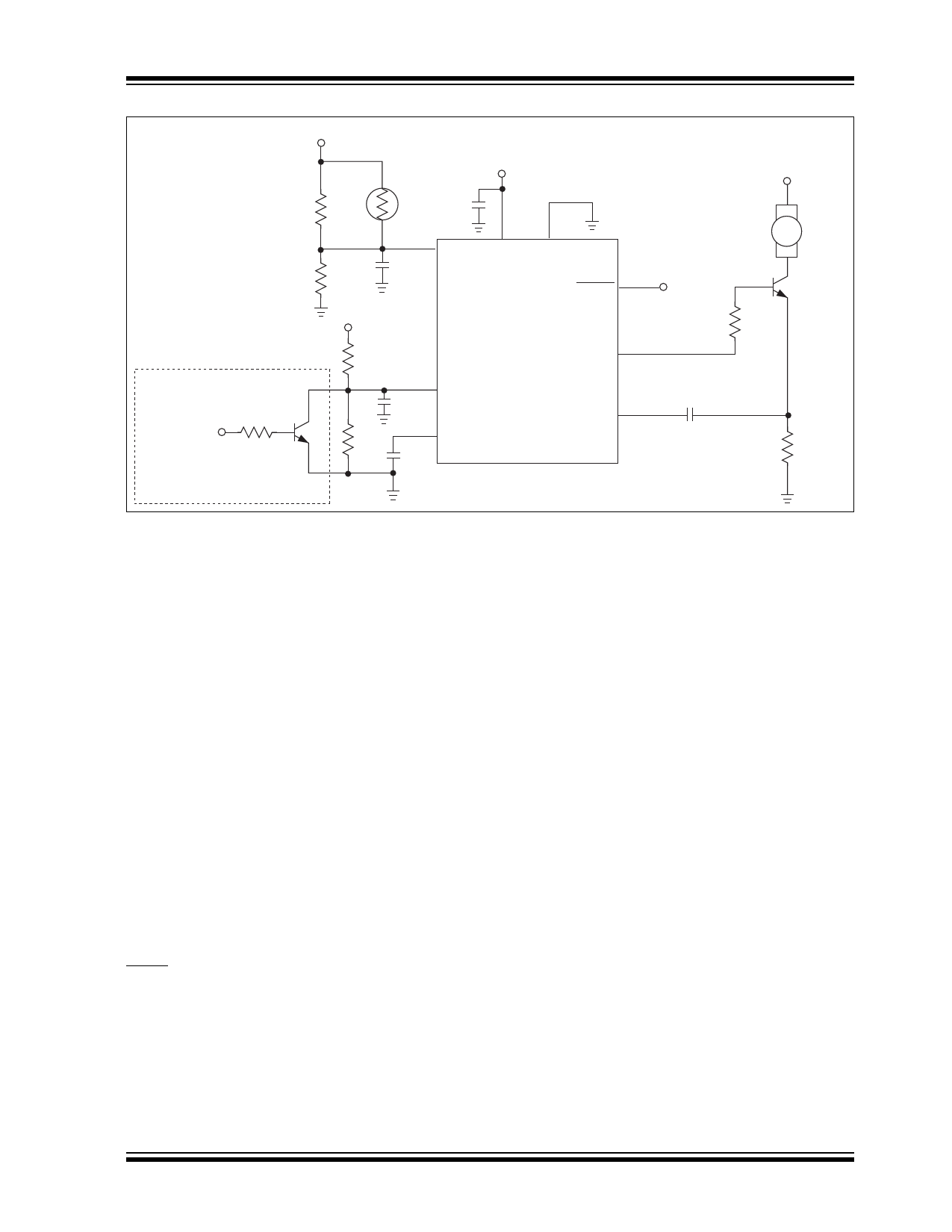
FIGURE 5-9:
Design Example.
5.8 TC647 as a Microcontroller
Peripheral
In a system containing a microcontroller or other host
intelligence, the TC647 can be effectively managed as
a CPU peripheral. Routine fan control functions can be
performed by the TC647 without controller intervention.
The microcontroller receives temperature data from one
or more points throughout the system. It calculates a fan
operating speed based on an algorithm specifically
designed for the application at hand. The processor
controls fan speed using complimentary port bits I/O1
through I/O3. Resistors R1 through R6 (5% tolerance)
form a crude 3-bit DAC that translates the 3-bit code
from the controller or processor's outputs into a 1.6V DC
control signal. A monolithic DAC or digital pot may be
used instead of the circuit shown in Figure 5-10.
With VMIN set to 1.8V, the TC647 has a minimum
operating speed of approximately 40% of full rated
speed when the processor's output code is 000[B].
Output codes 001[B] to 111[B] operate the fan from
roughly 40% to 100% of full speed. An open-drain
output from the processor I/O can be used to reset the
TC647 following detection of a fault condition. The
FAULT output can be connected to the processor's
interrupt input, or to an I/O pin, for polled operation (see
Figure 5-10).
System
Fault
CSENSE
0.1 µF
+12V
Fan
Q1
R7
800 Ω
RSENSE
2.2 Ω
2002 Microchip Technology Inc.
DS21447C-page 15
Share Link: 