TC642B View Datasheet(PDF) - Microchip Technology
Part Name
Description
Manufacturer
TC642B Datasheet PDF : 36 Pages
| |||
TC642B/TC647B
+5V
R1
237 k
R2
45.3 k
Thermometrics®
100 k @25°C
NHQ104B425R5
8
CB
1 VIN
VDD
0.01 µF
+ CVDD
1.0 µF
FAULT 6
+5V
R4
17.8 k
R3
32.4 k
CB 3 VMIN
0.01 µF
2 CF
CF
1.0 µF
TC647B VOUT 7
SENSE 5
GND
4
R5
10 k
+12V
Panasonic®
Fan 12V, 140 mA
FBA06T12H
Q1
SI2302
or
MGSF1N02E
CSENSE
0.1 µF
RSENSE
3.0
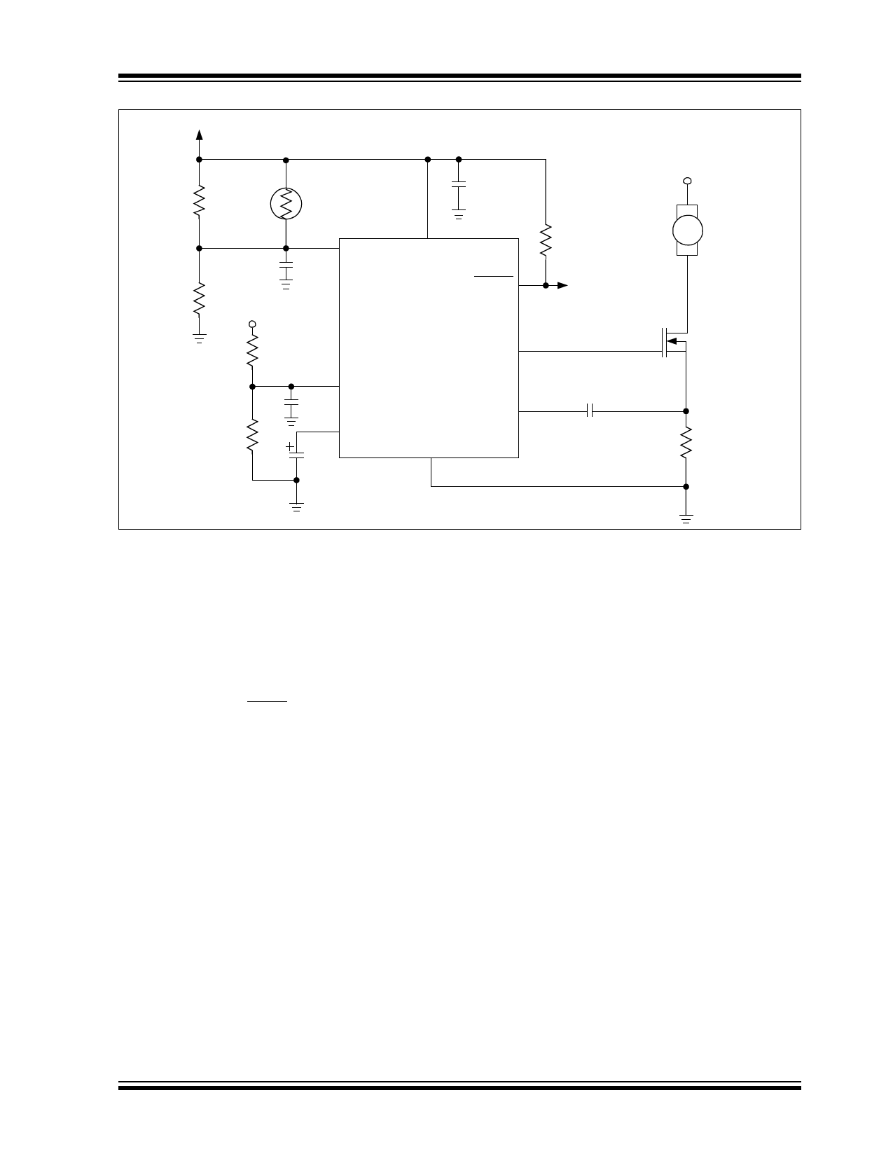
FIGURE 5-13:
Design Example Schematic.
Bypass capacitor CVDD is added to the design to
decouple the bias voltage. This is good to have, espe-
cially when using a MOSFET as the drive device. This
helps to give a localized low-impedance source for the
current required to charge the gate capacitance of Q1.
Two other bypass capacitors, labeled as CB, were also
added to decouple the VIN and VMIN nodes. These
were added simply to remove any noise present that
might cause false triggerings or PWM jitter. R5 is the
pull-up resistor for the FAULT output. The value for this
resistor is system-dependent.
2002-2013 Microchip Technology Inc.
DS21756C-page 25
Share Link: 