TC7126 View Datasheet(PDF) - TelCom Semiconductor Inc => Microchip
Part Name
Description
Manufacturer
TC7126 Datasheet PDF : 13 Pages
| |||
TC7126
TC7126A
3-1/2 DIGIT
ANALOG-TO-DIGITAL CONVERTERS
When a segment driver is in-phase with the backplane
signal, the segment is OFF. An out-of-phase segment drive
signal causes the segment to be ON, or visible. This AC drive
configuration results in negligible DC voltage across each
LCD segment, ensuring long LCD life. The polarity segment
driver is ON for negative analog inputs. If VIN+ and VIN– are
reversed, this indicator would reverse.
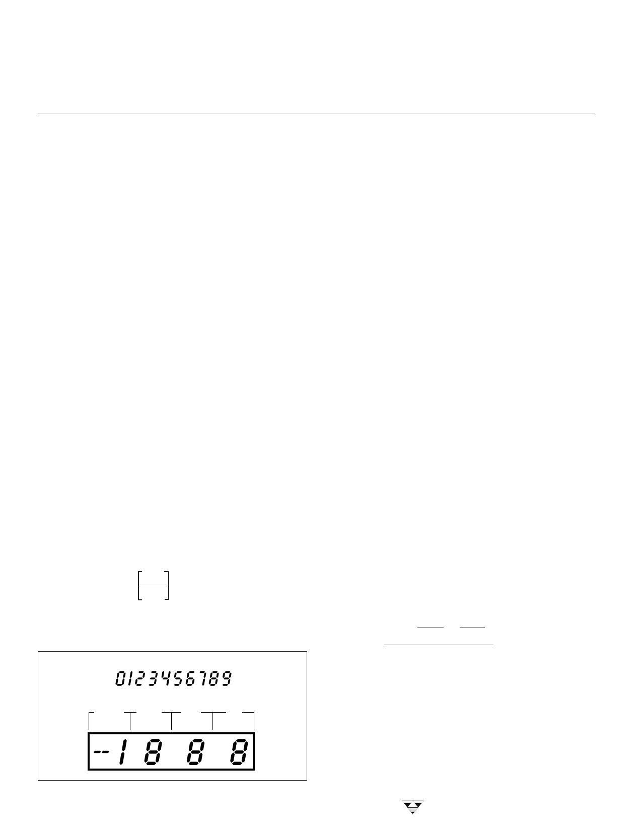
On the TC7126A, when the TEST pin is pulled to V+, all
segments are turned ON. The display reads –1888. During
this mode, LCD segments have a constant DC voltage
impressed. DO NOT LEAVE THE DISPLAY IN THIS MODE
FOR MORE THAN SEVERAL MINUTES; LCDS MAY BE
DESTROYED IF OPERATED WITH DC LEVELS FOR
EXTENDED PERIODS.
The display font and segment drive assignment are
shown in Figure 4.
System Timing
The oscillator frequency is Ϭ4 prior to clocking the
internal decade counters. The three-phase measurement
cycle takes a total of 4000 counts (16,000 clock pulses).
The 4000-count cycle is independent of input signal magni-
tude.
Each phase of the measurement cycle has the following
length:
(1) Auto-zero phase: 1000 to 3000 counts
(4000 to 12,000 clock pulses)
For signals less than full scale, the auto-zero phase
is assigned the unused reference integrate time
period.
(2) Signal integrate: 1000 counts
(4000 clock pulses)
This time period is fixed. The integration period is:
1
tSI = 4000 fOSC ,
where fOSC is the externally-set clock frequency.
(3) Reference integrate: 0 to 2000 counts
(0 to 8000 clock pulses)
DISPLAY FONT
1000's 100's
10's
1's
3-224
Figure 4. Display Font and Segment Assignment
The TC7126A is a drop-in replacement for the TC7126
and ICL7126 that offers a greatly improved internal refer-
ence temperature coefficient. No external component value
changes are required to upgrade existing designs.
COMPONENT VALUE SELECTION
Auto-Zero Capacitor (CAZ)
The CAZ size has some influence on system noise. A
0.33 µF capacitor is recommended for 200 mV full-scale
applications where 1 LSB is 100 µV. A 0.033 µF capacitor is
adequate for 2V full-scale applications. A Mylar-type dielec-
tric capacitor is adequate.
Reference Voltage Capacitor (CREF)
The reference voltage, used to ramp the integrator
output voltage back to zero during the reference integrate
phase, is stored on CREF. A 0.1 µF capacitor is acceptable
when VREF– is tied to analog common. If a large common-
mode voltage exists (VREF– ≠ analog common) and the
application requires a 200 mV full scale, increase CREF to
1 µF. Roll-over error will be held to less than 0.5 count. A
Mylar-type dielectric capacitor is adequate.
Integrating Capacitor (CINT)
CINT should be selected to maximize integrator output
voltage swing without causing output saturation. Due to
the TC7126A's superior analog common temperature co-
efficient specification, analog common will normally sup-
ply the differential voltage reference. For this case, a ±2V
full-scale integrator output swing is satisfactory. For 3
readings per second (fOSC = 48 kHz), a 0.047 µF value is
suggested. For 1 reading per second, 0.15 µF is recom-
mended. If a different oscillator frequency is used, CINT
must be changed in inverse proportion to maintain the
nominal ±2V integrator swing.
An exact expression for CINT is:
( ) ( ) (4000)
CINT =
1
fOSC
VFS
RINT ,
VINT
where: fOSC = Clock frequency at pin 38
VFS = Full-scale input voltage
RINT = Integrating resistor
VINT = Desired full-scale integrator output swing.
At 3 readings per second, a 750Ω resistor should be
placed in series with CINT. This increases accuracy by
compensating for comparator delay. CINT must have low
dielectric absorption to minimize roll-over error. A polypro-
pylene capacitor is recommended.
TELCOM SEMICONDUCTOR, INC.
Share Link: 