TC7129 View Datasheet(PDF) - TelCom Semiconductor Inc => Microchip
Part Name
Description
Manufacturer
TC7129
TelCom Semiconductor Inc => Microchip

TC7129 Datasheet PDF : 15 Pages
| |||
4-1/2 DIGIT ANALOG-TO-DIGITAL
CONVERTER WITH ON-CHIP LCD DRIVERS
TC7129
RC Oscillator
For applications in which 3-1/2 digit (100 µV) resolution
is sufficient, an RC oscillator is adequate. A recommended
value for the capacitor is 51 pF. Other values can be used as
long as they are sufficiently larger than the circuit parasitic
capacitance. The resistor value is calculated from:
R = 0.45
freq * C
For 120 kHz frequency and C = 51 pF, the calculated
value of R is 75 kΩ. The RC oscillator and the crystal
oscillator circuits are shown in Figure 8.
Measuring Techniques
Two important techniques are used in the TC7129:
successive integration and digital auto-zeroing. Successive
integration is a refinement to the traditional dual-slope
conversion technique.
measurement of the time to ramp the integrated voltage to
zero, and is therefore proportional to the input voltage being
measured. This count can then be scaled and displayed as
a measurement of the input voltage. Figure 9 shows the
phases of the dual-slope conversion.
The dual-slope method has a fundamental limitation.
The count can only stop on a clock cycle, so that measure-
ment accuracy is limited to the clock frequency. In addition,
a delay in the zero-crossing comparator can add to the
inaccuracy. Figure 10 shows these errors in an actual
measurement.
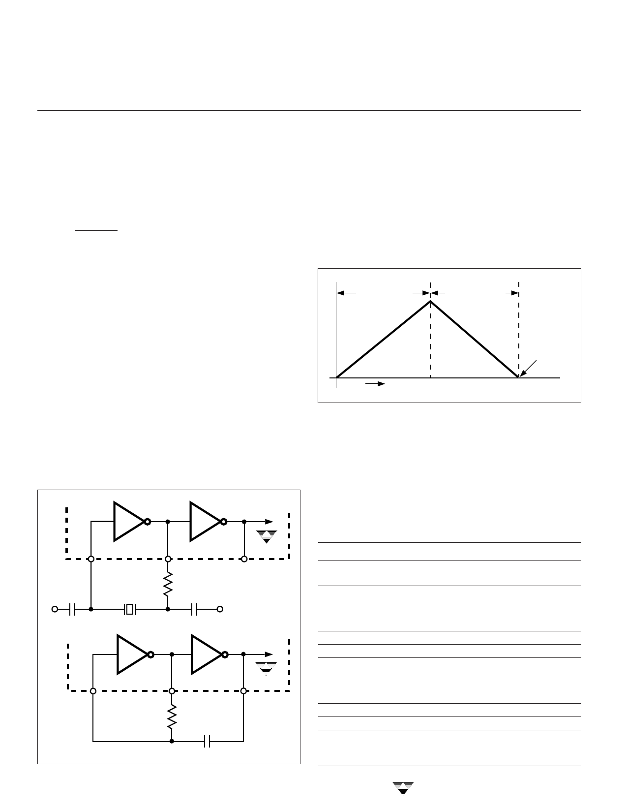
INTEGRATE
DEINTEGRATE
ZERO
CROSSING
Dual-Slope Conversion
A dual-slope conversion has two basic phases: inte-
grate and deintegrate. During the integrate phase, the input
signal is integrated for a fixed period of time; the integrated
voltage level is thus proportional to the input voltage. During
the deintegrate phase, the integrated voltage is ramped
down at a fixed slope, and a counter counts the clock cycles
until the integrator voltage crosses zero. The count is a
TIME
Figure 9. Dual-Slope Conversion
Successive Integration
The successive integration technique picks up where
dual-slope conversion ends. The overshoot voltage shown
in Figure 10, called the "integrator residue voltage," is
measured to obtain a correction to the initial count. Figure 11
shows the cycles in a successive integration measurement.
The waveform shown is for a negative input signal. The
sequence of events during the measurement cycle is:
1
5 pF
V+
120 kHz
40
270 kΩ
10 pF
TC7129
2
V+
3-240
TC7129
1
40
2
75 kΩ
51 pF
Figure 8. Oscillator Circuits
Phase
INT1
DE1
REST
X10
DE2
REST
X10
DE3
Description
Input signal is integrated for fixed time. (1000 clock
cycles on 2V scale, 10,000 on 200 mV)
Integrator voltage is ramped to zero. Counter counts
up until zero crossing to produce reading accurate
to 3-1/2 digits. Residue represents an overshoot of
the actual input voltage.
Rest; circuit settles.
Residue voltage is amplified 10 times and inverted.
Integrator voltage is ramped to zero. Counter counts
down until zero crossing to correct reading to 4-1/2
digits. Residue represents an undershoot of the
actual input voltage.
Rest; circuit settles.
Residue voltage is amplified 10 times and inverted.
Integrator voltage is ramped to zero. Counter counts
up until zero crossing to correct reading to 5-1/2
digits. Residue is discarded.
TELCOM SEMICONDUCTOR, INC.
Share Link: