TC7136 View Datasheet(PDF) - TelCom Semiconductor Inc => Microchip
Part Name
Description
Manufacturer
TC7136 Datasheet PDF : 12 Pages
| |||
TC7136
TC7136A
LOW POWER, 3-1/2 DIGIT
ANALOG-TO-DIGITAL CONVERTERS
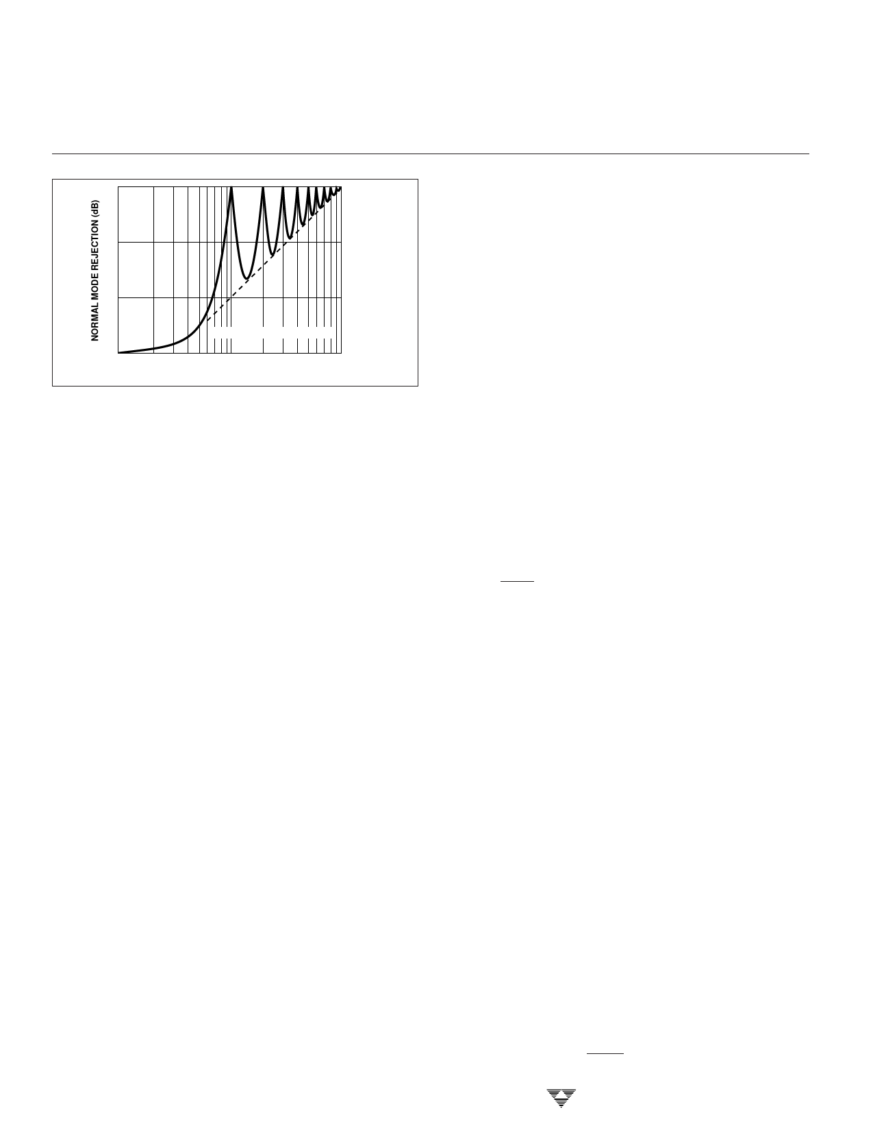
30
20
10
t = MEASUREMENT PERIOD
0
0.1/t
1/t
10/t
INPUT FREQUENCY
Figure 2. Normal-Mode Rejection of Dual-Slope Converter
The dual-slope converter accuracy is unrelated to the
integrating resistor and capacitor values, as long as they are
stable during a measurement cycle. Noise immunity is an
inherent benefit. Noise spikes are integrated, or averaged,
to zero during integration periods. Integrating ADCs are
immune to the large conversion errors that plague succes-
sive approximation converters in high-noise environments.
Interfering signals with frequency components at multiples
of the averaging period will be attenuated. Integrating ADCs
commonly operate with the signal integration period set to a
multiple of the 50 Hz/60 Hz power line period.
ANALOG SECTION
In addition to the basic integrate and deintegrate dual-
slope cycles discussed above, the TC7136/A designs incor-
porate an "integrator output-zero cycle" and an "auto-zero
cycle." These additional cycles ensure the integrator starts
at 0V (even after a severe overrange conversion) and that all
offset voltage errors (buffer amplifier, integrator and com-
parator) are removed from the conversion. A true digital zero
reading is assured without any external adjustments.
A complete conversion consists of four distinct phases:
(1) Integrator output-zero phase
(2) Auto-zero phase
(3) Signal integrate phase
(4) Reference deintegrate phase
Integrator Output-Zero Phase
This phase guarantees the integrator output is at 0V
before the system-zero phase is entered. This ensures that
true system offset voltages will be compensated for even
after an overrange conversion. The count for this phase is a
function of the number of counts required by the deintegrate
phase.
The count lasts from 11 to 140 counts for non-overrange
conversions and from 31 to 640 counts for overrange
conversions.
3-252
Auto-Zero Phase
During the auto-zero phase, the differential input signal
is disconnected from the circuit by opening internal analog
gates. The internal nodes are shorted to analog common
(ground) to establish a zero input condition. Additional
analog gates close a feedback loop around the integrator
and comparator. This loop permits comparator offset volt-
age error compensation. The voltage level established on
CAZ compensates for device offset voltages. The auto-zero
phase residual is typically 10 µV to 15 µV.
The auto-zero duration is from 910 to 2900 counts for
non-overrange conversions and from 300 to 910 counts for
overrange conversions.
Signal Integration Phase
The auto-zero loop is entered and the internal differen-
tial inputs connect to VI+N and VIN– . The differential input signal
is integrated for a fixed time period. The TC7136/A signal
integration period is 1000 clock periods or counts. The
externally-set clock frequency is divided by four before
clocking the internal counters. The integration time period is:
4
tSI = fOSC ϫ 1000,
where fOSC = external clock frequency.
The differential input voltage must be within the device
common-mode range when the converter and measured
system share the same power supply common (ground). If
the converter and measured system do not share the same
power supply common, VIN– should be tied to analog com-
mon.
Polarity is determined at the end of signal integrate
phase. The sign bit is a true polarity indication, in that signals
less than 1 LSB are correctly determined. This allows
precision null detection limited only by device noise and
auto-zero residual offsets.
Reference Integrate Phase
is
The third phase is reference integrate or
internally connected to analog common
daenidntVegI+Nraistec.oVnI–N-
nected across the previously-charged reference capacitor.
Circuitry within the chip ensures that the capacitor will be
connected with the correct polarity to cause the integrator
output to return to zero. The time required for the output to
return to zero is proportional to the input signal and is
between 0 and 2000 internal clock periods. The digital
reading displayed is:
1000 VIN
VREF
TELCOM SEMICONDUCTOR, INC.
Share Link: 