TDA2579C View Datasheet(PDF) - Philips Electronics
Part Name
Description
Manufacturer
TDA2579C
Philips Electronics

TDA2579C Datasheet PDF : 24 Pages
| |||
Philips Semiconductors
Synchronization circuit with synchronized
vertical divider system for 60 Hz
Preliminary specification
TDA2579C
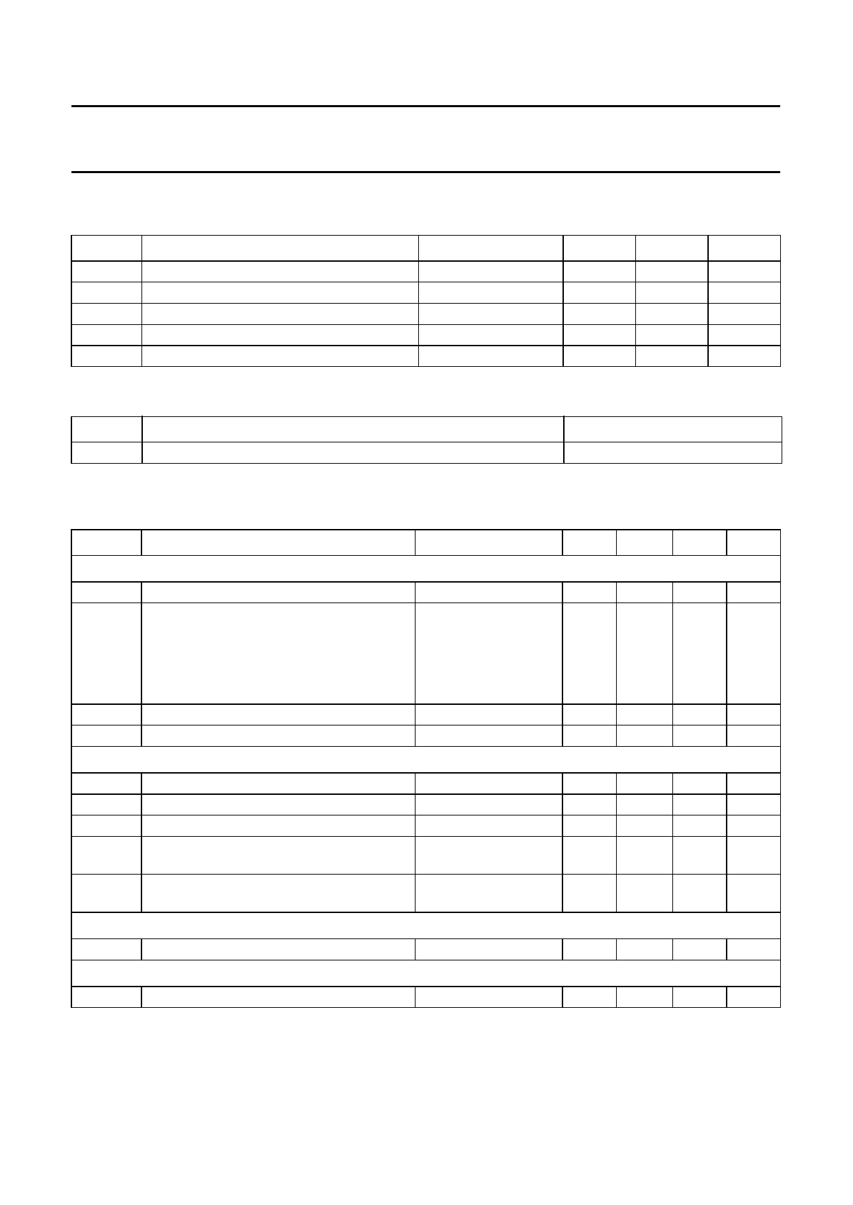
LIMITING VALUES
In accordance with Absolute Maximum Rating System (IEC 134).
SYMBOL
PARAMETER
CONDITIONS
I16
VP
Ptot
Tstg
Tamb
start current
supply voltage
total power dissipation
storage temperature
operating ambient temperature
V10 = 0 V
MIN.
−
−
−
−55
−25
MAX.
9.7
13.2
1.2
+150
+70
UNIT
mA
V
W
°C
°C
THERMAL RESISTANCE
SYMBOL
PARAMETER
Rth j-a
from junction to ambient in free air
THERMAL RESISTANCE
50 K/W
CHARACTERISTICS
VP = V10 = 12 V; I16 = 6.2 mA; Tamb = 25 °C; unless otherwise specified.
SYMBOL
PARAMETER
CONDITIONS
Supply
VP
I16
supply voltage (pin 10)
supply current (pin 16)
V16
stabilized voltage (pin 16)
I10
current consumption (pin 10)
Video input (pin 5)
V5
V5(p-p)
SL
top sync level
sync pulse amplitude (peak-to-peak value)
slicing level
td
delay between video input and detector
output
S/N
signal-to-noise ratio with sync pulse noise
level detector circuit active
note 1
V10 = 0 V
V10 = 1 to 10 V;
Tamb ≤ 70 °C
V10 > 10 V
note 2
note 3
see Fig.5
CVBS = 1 V without
filter at pin 5; note 4
Sync pulse
HYS
noise level detector circuit hysteresis
Noise gate (pin 5)
V5
switching level
MIN. TYP. MAX. UNIT
10
12
13.2 V
6.2
−
6.2
−
9.7
mA
8.7
mA
2.5
−
9.7
mA
8.8
9.3
9.7
V
−
70
85
mA
1.5
3.1
0.05 0.6
35
50
0.2
0.3
−
19
3.75 V
1
V
65
%
0.55 µs
−
dB
−
3
−
dB
−
0.7
1
V
January 1994
11
Share Link: