TDA2579C View Datasheet(PDF) - Philips Electronics
Part Name
Description
Manufacturer
TDA2579C
Philips Electronics

TDA2579C Datasheet PDF : 24 Pages
| |||
Philips Semiconductors
Synchronization circuit with synchronized
vertical divider system for 60 Hz
Preliminary specification
TDA2579C
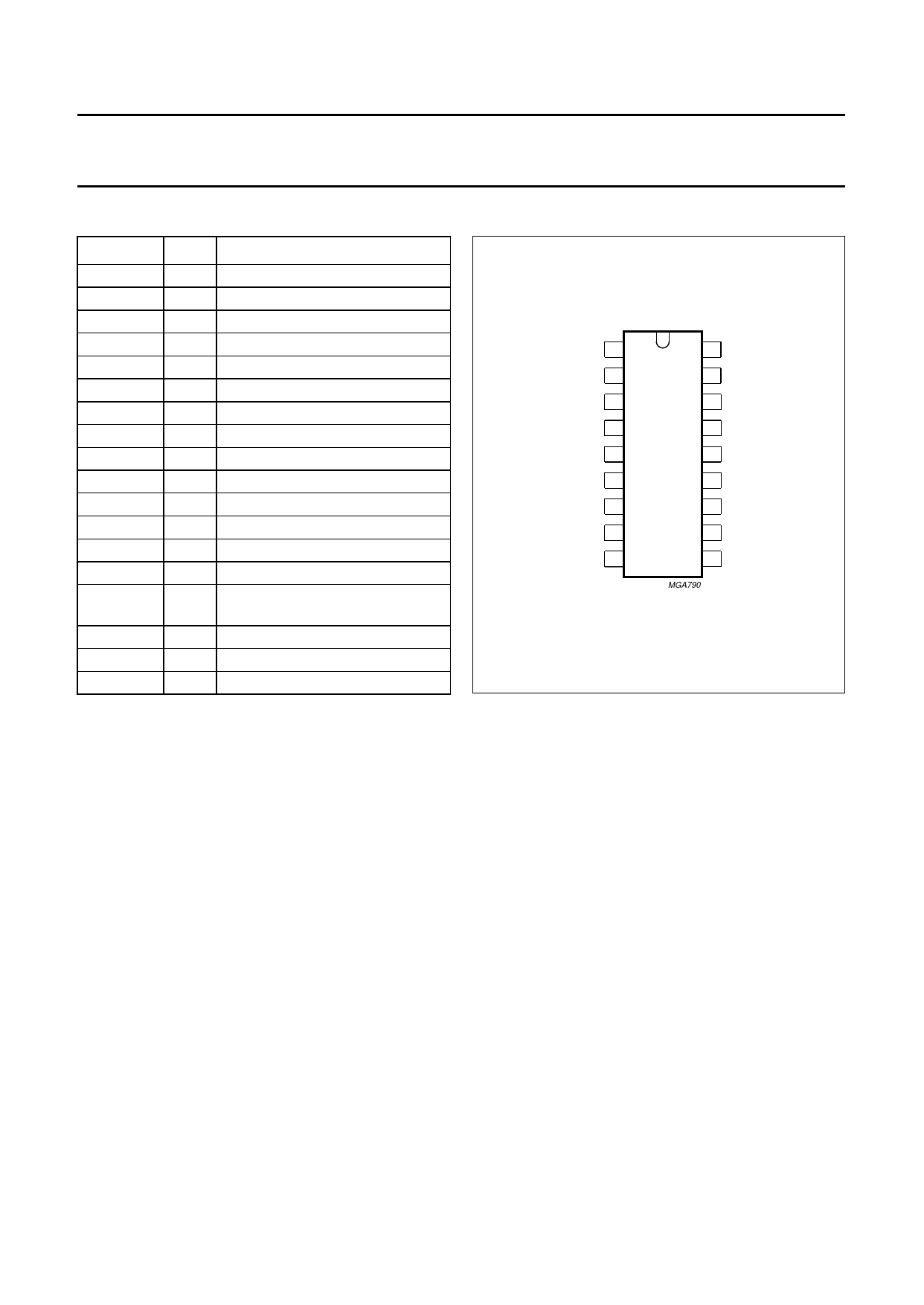
PINNING
SYMBOL
VOUT
FB
SAW
VDC
VID
CSL
RSL
ϕ1
GND
VP
HOUT
FLYB
MUTE
HSHIFT
HOSC
STAB
SC
DET
PIN
DESCRIPTION
1 vertical driver output
2 vertical feedback input
3 vertical sawtooth generator
4 vertical deflection current output
5 video signal input
6 slicing level storage capacitor
7 slicing level resistor
8 phase detector ϕ1
9 ground (0 V)
10 main supply voltage (+12 V)
11 horizontal driver output
12 horizontal flyback pulse input
13 mute output
14 horizontal picture shift capacitor
15 horizontal oscillator frequency
setting
16 start circuit stabilizer input
17 sandcastle output
18 coincidence detector output
VOUT 1
18 DET
FB 2
17 SC
SAW 3
16 STAB
VDC 4
VID 5
CSL 6
TDA2579C
15 H OSC
14 H SHIFT
13 MUTE
RSL 7
ϕ1 8
GND 9
12 FLYB
11 H OUT
10 VP
MGA790
Fig.2 Pin configuration.
FUNCTIONAL DESCRIPTION
The TDA2579C generates both horizontal and vertical
drive signals, a 3-level sandcastle output pulse, a
transmitter identification signal and 60 Hz window
information.
The horizontal oscillator and horizontal output stage
functions are started via the supply current into pin 16.
The required current has a typical value of 5 mA which can
be taken directly from the mains rectifier. The horizontal
output transistor at pin 11 is not conducting until the supply
current at pin 16 has reached its typical value. The starting
circuit has a hysteresis of approximately 1 mA. The
horizontal output current of pin 11 starts at a duty cycle of
60%. All other IC functions are enabled via the main supply
voltage on pin 10.
The pin 16 supply system enables slaved synchronized
switch mode systems in which the horizontal output signal
of the TDA2579C is used as master signal. In such a
system the 12 V supply (main supply at pin 10) can be
generated by the line output stage.
An internal Zener diode reference voltage is used for the
vertical processing part. The IC embodies a synchronized
divider system for generating the vertical sawtooth at
pin 3. Thus no vertical frequency adjustment is required.
The circuit operation is restricted to the M (fV = 60 Hz)
system.
Vertical part (pins 1, 2, 3 and 4)
The IC embodies a synchronized divider system for
generating the vertical sawtooth at pin 3. The divider
system has an internal frequency doubling circuit, thus the
horizontal oscillator is operating at its nominal line
frequency and one line period equals 2 clock pulses.
No vertical frequency adjustment is required due to the
divider system. The divider system operates with
3 different reset windows for maximum
interference/disturbance protection.
The windows are activated via an up/down counter.
The counter increases its value by 1 each time the
separated vertical sync pulse is within the window being
searched. The count is reduced by 1 when the vertical
sync pulse is not present.
The reset of the counter system (clock pulse 0) is at half a
line period after the start of the vertical pulse at pin 5.
January 1994
5
Share Link: