TDA2579C View Datasheet(PDF) - Philips Electronics
Part Name
Description
Manufacturer
TDA2579C
Philips Electronics

TDA2579C Datasheet PDF : 24 Pages
| |||
Philips Semiconductors
Synchronization circuit with synchronized
vertical divider system for 60 Hz
Preliminary specification
TDA2579C
mute
(pin 13)
gating
ϕ1 detector
ϕ1 detector
I8 0.35 mA
ϕ2 detector
I8 1.0 mA
not gated
ϕ3 detector
I8 0.65 mA
not gated
voltage
(pin 18)
1
0
1
0
1
0
1
0
1
A
0.1 V
0
B
C
D
E
F
G
1.2 V 1.8 V
3.5 V
5V
7.8 V
MGA792
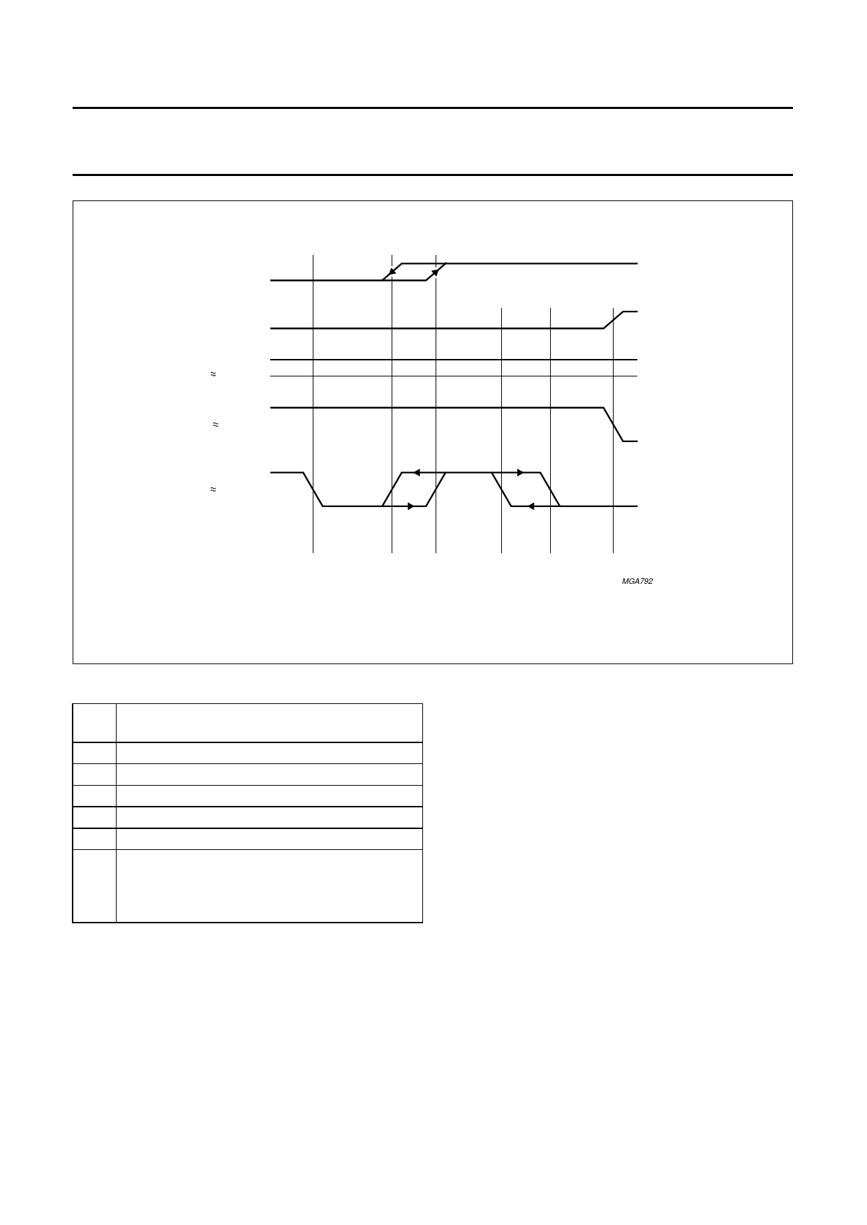
Fig.3 Operation of the three phase detector circuits.
Explanation of areas A to G shown in Fig.3
A switching over to new TV station activates 3 field
period counter
B noise only condition
C TV transmitter identification hysteresis range
D fast time constant
C-E fast time constant hysteresis range
F normal time constant
G sync pulse noise level detection circuit forces
pin 18 to >7.8 V while signal-to-noise level
<19 dB; slow time constant and gated sync pulse
operation.
Supply (pins 9, 10 and 16)
The IC has been designed such that the horizontal
oscillator and output stage operate a very low supply
current into pin 16. The horizontal oscillator starts at a
supply current of approximately 4 mA (V16 approximately
6 V). The horizontal output stage is forced into the
non-conducting stage until the supply current has reached
a typical value of 5 mA.
The circuit has been designed such that after starting the
horizontal output function, a current drop of approximately
1 mA is allowed.
The starting circuit has the ability to derive the main supply
(pin 10) from the horizontal output stage. The horizontal
output signal can also be used as oscillator signal for
synchronized switched-mode power supplies.
January 1994
9
Share Link: