LTC1772HS6 View Datasheet(PDF) - Linear Technology
Part Name
Description
Manufacturer
LTC1772HS6 Datasheet PDF : 12 Pages
| |||
LTC1772
U
OPERATIO (Refer to Functional Diagram)
Slope Compensation and Inductor’s Peak Current
The inductor’s peak current is determined by:
( ) IPK
=
VITH – 0.7
10 RSENSE
when the LTC1772 is operating below 40% duty cycle.
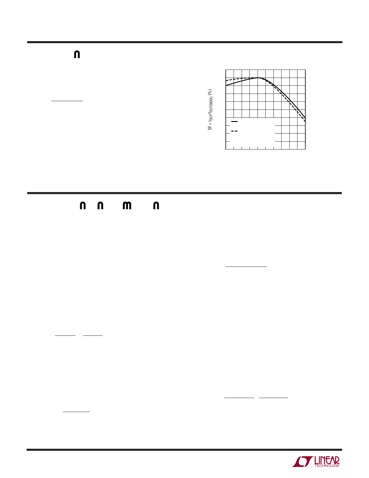
However, once the duty cycle exceeds 40%, slope com-
pensation begins and effectively reduces the peak induc-
tor current. The amount of reduction is given by the curves
in Figure 2.
110
100
90
80
70
60
50
40
IRIPPLE = 0.4IPK
AT 5% DUTY CYCLE
30
IRIPPLE = 0.2IPK
AT 5% DUTY CYCLE
20
VIN = 4.2V
10
0 10 20 30 40 50 60 70 80 90 100
DUTY CYCLE (%)
1772 F02
Figure 2. Maximum Output Current vs Duty Cycle
APPLICATIONS INFORMATION
The basic LTC1772 application circuit is shown in Figure 1.
External component selection is driven by the load re-
quirement and begins with the selection of L1 and RSENSE
(= R1). Next, the power MOSFET, M1 and the output diode
D1 are selected followed by CIN (= C1) and COUT (= C2).
RSENSE Selection for Output Current
RSENSE is chosen based on the required output current.
With the current comparator monitoring the voltage devel-
oped across RSENSE, the threshold of the comparator
determines the inductor’s peak current. The output cur-
rent the LTC1772 can provide is given by:
IOUT
=
0.12
RSENSE
−
IRIPPLE
2
where IRIPPLE is the inductor peak-to-peak ripple current
(see Inductor Value Calculation section).
A reasonable starting point for setting ripple current is
IRIPPLE = (0.4)(IOUT). Rearranging the above equation, it
becomes:
RSENSE =
1 for Duty Cycle
(10)(IOUT )
< 40%
However, for operation that is above 40% duty cycle, slope
compensation effect has to be taken into consideration to
select the appropriate value to provide the required amount
of current. Using Figure 2, the value of RSENSE is:
RSENSE
=
SF
(10)(IOUT )(100)
Inductor Value Calculation
The operating frequency and inductor selection are inter-
related in that higher operating frequencies permit the use
of a smaller inductor for the same amount of inductor
ripple current. However, this is at the expense of efficiency
due to an increase in MOSFET gate charge losses.
The inductance value also has a direct effect on ripple
current. The ripple current, IRIPPLE, decreases with higher
inductance or frequency and increases with higher VIN or
VOUT. The inductor’s peak-to-peak ripple current is given
by:
IRIPPLE =
VIN
− VOUT
f(L)
⎛
⎝⎜
VOUT + VD
VIN + VD
⎞
⎠⎟
1772fb
6
Share Link: 