VIPER26 View Datasheet(PDF) - STMicroelectronics
Part Name
Description
Manufacturer
VIPER26 Datasheet PDF : 25 Pages
| |||
Electrical data
VIPER26
4.3
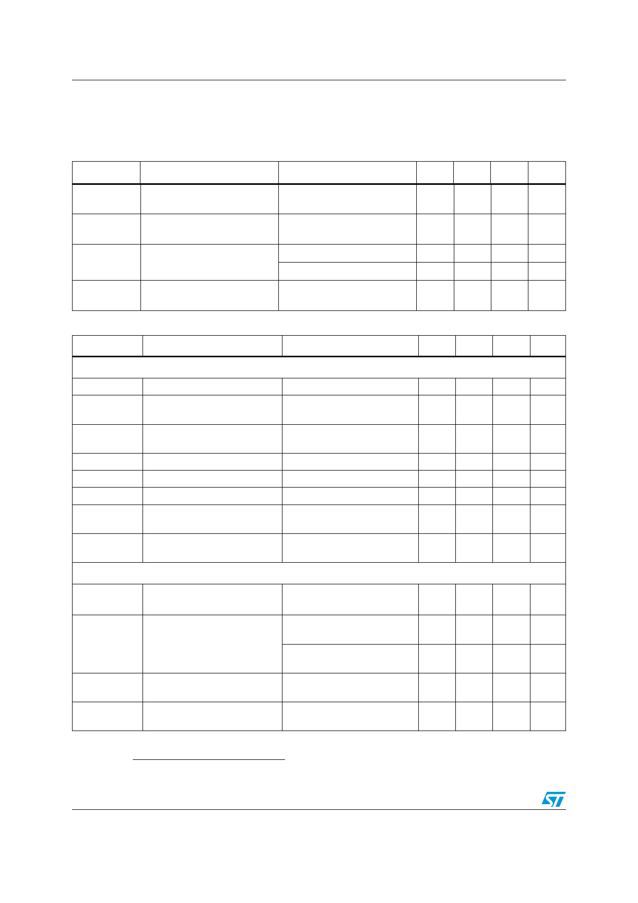
Electrical characteristics
(TJ = -25 to 125 °C, VDD = 14 V (a); unless otherwise specified)
Table 6. Power section
Symbol
Parameter
Test condition
Min Typ Max Unit
VBVDSS Break-down voltage
IOFF
RDS(on)
COSS
OFF state drain current
Drain-source on state
resistance
Effective (energy related)
output capacitance
IDRAIN = 1 mA,
VCOMP = GND, TJ = 25 °C
VDRAIN = max rating,
VCOMP = GND
IDRAIN = 0.2 A, TJ = 25 °C
IDRAIN = 0.2 A, TJ = 125 °C
VDRAIN = 0 to 640 V
800
V
60
µA
7
Ω
14
Ω
40
pF
Table 7. Supply section
Symbol
Parameter
Test condition
Voltage
VDRAIN_START
IDDch1
IDDch2
VDD
VDDclamp
VDDon
VDDCSon
VDDoff
Current
IDD0
IDD1
IDDoff
IDDol
Drain-source start voltage
Charging current during the
start up
Charging current during the
autorestart
Operating voltage range
VDD clamp voltage
VDD start up threshold
VDD on internal high voltage
current generator threshold
VDD under voltage shutdown
threshold
Operating supply current, not
switching
Operating supply current,
switching
Operating supply current with
VDD < VDDoff
Open loop failure current
threshold
VDRAIN = 100 V to 640 V,
VDD = 4 V
VDRAIN = 100 V to 640 V,
VDD = 9 V falling edge
IDD = 15 mA
FOSC = 0 kHz,
VCOMP = GND
VDRAIN = 120 V,
FSW = 60 kHz
VDRAIN = 120 V,
FSW = 115 kHz
VDD < VDDoff
VDD = VDDclamp
VCOMP = 3.3 V,
Min Typ Max Unit
60
80 100
V
-0.6
-1.8 mA
-7
-13 mA
11.5
23.5 V
23.5
V
12
13
14
V
9.5 10.5 11.5 V
7
8
9
V
0.6 mA
2.5 mA
3.5 mA
0.35 mA
4
mA
6/25
a. Adjust VDD above VDDon startup threshold before setting to 14 V
Doc ID 17736 Rev 2
Share Link: 