W523S10 View Datasheet(PDF) - Winbond
Part Name
Description
Manufacturer
W523S10 Datasheet PDF : 14 Pages
| |||
W523SXX (PRELIMINARY)
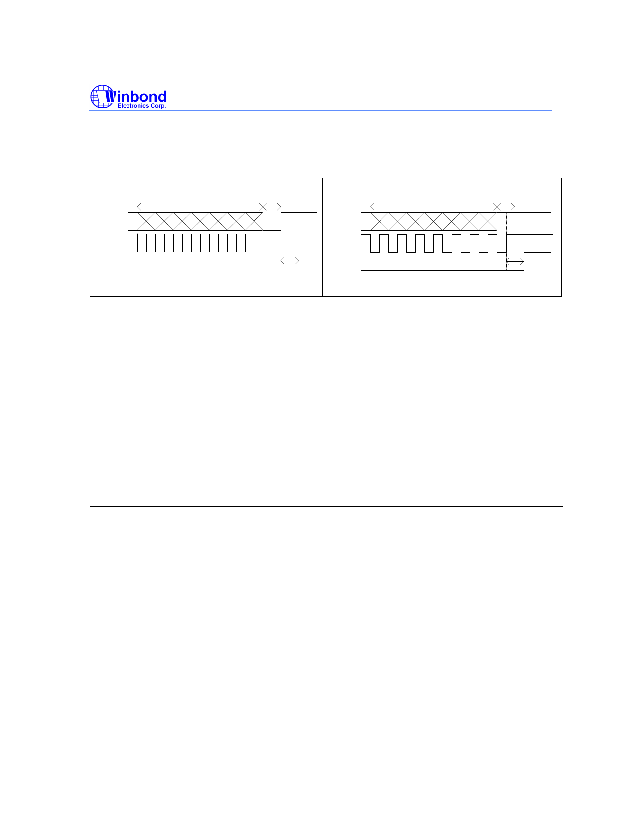
dependent on the MSB of data output on TG1 (Data) pin. If MSB is "1", Busy will rise after the last
rising edge of TG2 (Clock) pin. If MSB is "0", Busy will rise after the rising edge that TG1 (Data)
returns to high.
TG1
(DATA)
TG2
(CLK)
BUSY
7 bits
MSB=0
40ns
TG1
(DATA)
TG2
(CLK)
BUSY
7 bits
MSB=1
40ns
To place the W523Sxx in CPU mode, program the code according to the following example.
W523S15
CPU; Reserved word, used as a directive to notify the compiler for post processing.
LED1
FREQ2
POI:
LD MODE0,XX1XX0XXB
LD EN0, 0x00
H5+voice1+T5
END
;bit2=0 BUSY
34: ; Direct trigger or CPU interrupt.
H5+voice2+T5
END
The defaulted operating mode in W523Sxx is normal mode (or manual trigger mode), which is
identified by the "Normal" and "CPU" option control. To enter the CPU mode, the "CPU" declaration
must be inserted in the declaration region of program (*.out). In CPU mode, the bit MODE0.2, which is
defined as STPA or BUSY selection for the STPA/BUSY pin, will be selected as "0" (BUSY output)
automatically by the compiler unless otherwise specified explicitly by the STPA directive. The CPU,
STPA, and BUSY directives can appear only in the first paragraph of the *.out files so that the
compiler will automatically interpret them as Stop definitions in the POI interrupt vector. If these
directives are placed elsewhere, an error message will be issued during the compilation process.
In the program example shown above, the external µC will transfer one byte data "34" to W523Sxx.
The number 34 (Decimal) is equal to 00100010b (Binary). The interface timing is shown below.
-8-
Share Link: 