W83194BR-323 View Datasheet(PDF) - Winbond
Part Name
Description
Manufacturer
W83194BR-323 Datasheet PDF : 18 Pages
| |||
W83194BR-323W83194BG-323
STEPLESS CLOCK FOR INTEL BROOKDALE CHIPSET
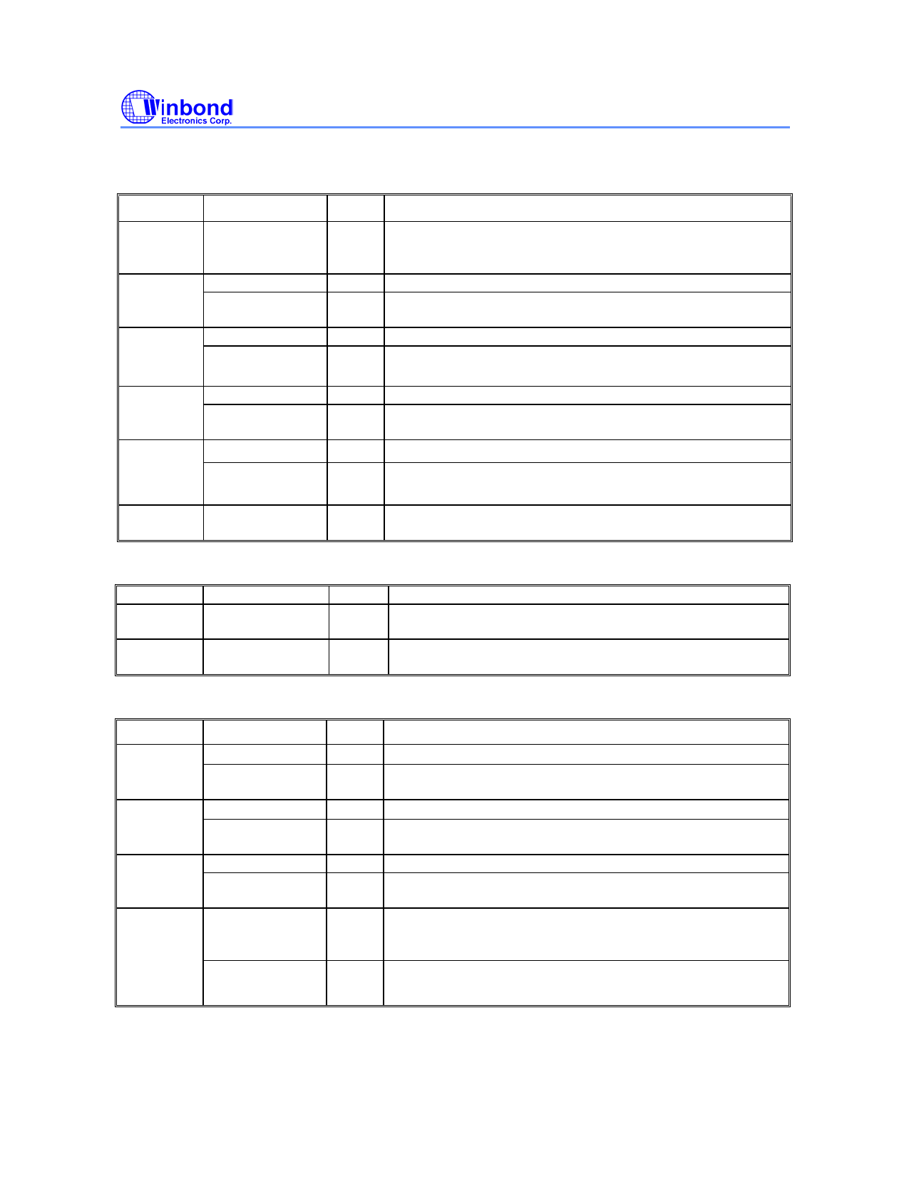
CPU, 3V66, and PCI Clock Outputs, continued
PIN
PIN NAME
TYPE
DESCRIPTION
42 PD#
6
PCICLK_F0
*FS2
7
PCICLK_F1
*FS3
8
PCICLK_F2
&SEL24_48
10 PCICLK0
IN Power Down Function. This is power down pin, low active
(PD#).
Internal 120K pull up
OUT 3.3V free running PCI clock output.
INtp120k Latched input for FS2 at initial power up for H/W selecting
the output frequency, This is internal 120K pull up.
OUT 3.3V free running PCI clock output.
INtp120k Latched input for FS3 at initial power up for H/W selecting
the output frequency, This is internal 120K pull up.
OUT 3.3V free running PCI clock outputs.
INtd120k Latched input for 24MHz or 48MHz select pin. This is internal
120K pull down default 24MHz.
OUT Low skew (< 250ps) PCI clock outputs.
*FS4
11, 12, 14, PCICLK [1:6]
15, 16, 17
INtP120k Latched input for FS4 at initial power up for H/W selecting
the output frequency, This is internal 120K pull up.
OUT Low skew (< 250ps) PCI clock outputs.
5.3 I2C Control Interface
PIN
Pin Name
25 SDATA*
26 SCLK*
Type
I/OD
IN
Description
Serial data of I2C 2-wire control interface with internal pull-
up resistor.
Serial clock of I2C 2-wire control interface with internal pull-
up resistor.
5.4 Fixed Frequency Outputs
PIN
PIN NAME
TYPE
DESCRIPTION
48 REF0
OUT 14.318NHz output.
MULTSEL0*
INtp120k Latched input for MULTSEL0 at initial power up, internal
120K pull up
1
REF1
OUT 14.318NHz output.
MULTSEL1*
22 48MHz
*FS0
23 24_48MHz
*FS1
INtp120k Latched input for MULTSEL1 at initial power up, internal
120K pull up
OUT 48MHz clock output for USB.
INtp120k Latched input for FS0 at initial power up for H/W selecting
the output frequency. This is internal 120K pull up.
OUT 24(default) or 48MHz clock output, In power on reset period,
it is a hardware-latched pin, and it can be R/W by I2C control
after power on reset period. Select by register 16 bit 7.
INtp120k Latched input for FS1 at initial power up for H/W selecting
the output frequency. This is internal 120K pull up.
-4-
Share Link: 