AXK8L60125BG View Datasheet(PDF) - Panasonic Corporation
Part Name
Description
Manufacturer
AXK8L60125BG Datasheet PDF : 7 Pages
| |||
AXK7L, 8L
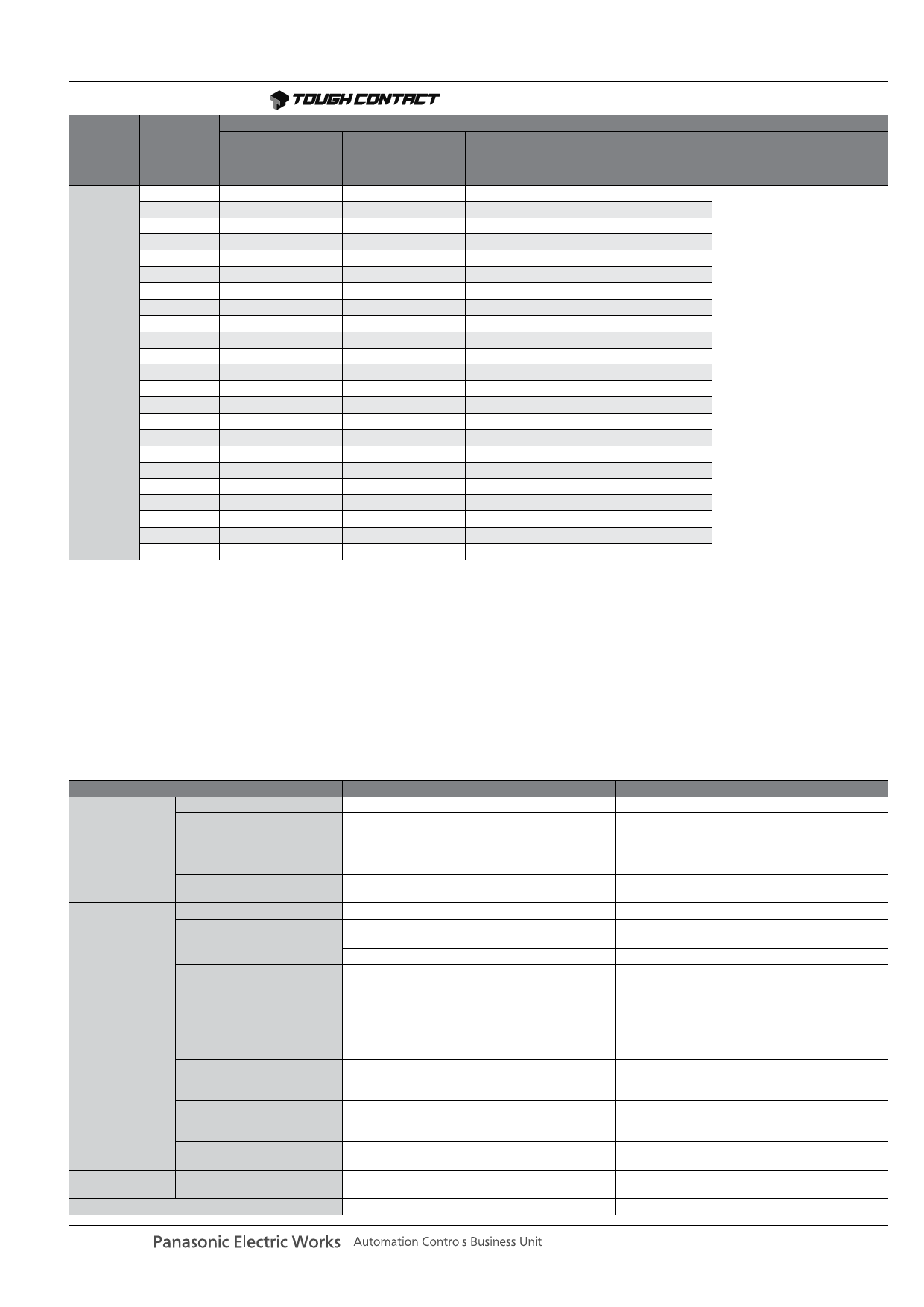
PRODUCT TYPES
Part number
Packing
Mated
height
Number of
contacts
Socket
Socket
Products with plating change
to soldering terminals
(in effect from Dec. ’09)
Header
Header
Products with plating change
to soldering terminals
(in effect from Dec. ’09)
Inner carton
(1 reel)
Outer carton
10
AXK7L10227G
AXK7L10223G
AXK8L10125BG
AXK8L10124BG
12
AXK7L12227G
AXK7L12223G
AXK8L12125BG
AXK8L12124BG
14
AXK7L14227G
AXK7L14223G
AXK8L14125BG
AXK8L14124BG
16
AXK7L16227G
AXK7L16223G
AXK8L16125BG
AXK8L16124BG
20
AXK7L20227G
AXK7L20223G
AXK8L20125BG
AXK8L20124BG
22
AXK7L22227G
AXK7L22223G
AXK8L22125BG
AXK8L22124BG
24
AXK7L24227G
AXK7L24223G
AXK8L24125BG
AXK8L24124BG
26
AXK7L26227G
AXK7L26223G
AXK8L26125BG
AXK8L26124BG
28
AXK7L28227G
AXK7L28223G
AXK8L28125BG
AXK8L28124BG
30
AXK7L30227G
AXK7L30223G
AXK8L30125BG
AXK8L30124BG
32
0.9 mm
34
36
AXK7L32227G
AXK7L34227G
AXK7L36227G
AXK7L32223G
AXK7L34223G
AXK7L36223G
AXK8L32125BG
AXK8L34125BG
AXK8L36125BG
AXK8L32124BG
AXK8L34124BG
AXK8L36124BG
3,000 pieces
6,000 pieces
(2 reels)
38
AXK7L38227G
AXK7L38223G
AXK8L38125BG
AXK8L38124BG
40
AXK7L40227G
AXK7L40223G
AXK8L40125BG
AXK8L40124BG
44
AXK7L44227G
AXK7L44223G
AXK8L44125BG
AXK8L44124BG
48
AXK7L48227G
AXK7L48223G
AXK8L48125BG
AXK8L48124BG
50
AXK7L50227G
AXK7L50223G
AXK8L50125BG
AXK8L50124BG
54
AXK7L54227G
AXK7L54223G
AXK8L54125BG
AXK8L54124BG
60
AXK7L60227G
AXK7L60223G
AXK8L60125BG
AXK8L60124BG
66
AXK7L66227G
AXK7L66223G
AXK8L66125BG
AXK8L66124BG
70
AXK7L70227G
AXK7L70223G
AXK8L70125BG
AXK8L70124BG
80
AXK7L80227G
AXK7L80223G
AXK8L80125BG
AXK8L80124BG
Notes: 1. Regarding ordering units;
During production: Please make orders in 1-reel units.
Samples for mounting confirmation: Available in units of 50 pieces. Please contact us.
Samples: Available. Please contact us.
2. The above part numbers are for connectors without positioning bosses, which are standard. When ordering connectors with positioning bosses, please contact our
sales office.
3. Please contact us regarding different number of contacts.
4. “B” in the 11th digit of the header part number signifies a fork type soldering terminals to lessen the constraint on amount of solder when mounting, and a
construction that makes it difficult when mounting for excess solder to interfere with the socket.
Although compatible with the previous parts, these parts are not compatible with the recommended PC board pattern and recommended metal mask pattern.
5. Since the plating specifications for the metal clips will be changed starting with production in December 2009 onwards, the digit “7” in the 10th place of the part
number for sockets will be changed to “3”, and “5” for headers will be changed to “4”.
Be careful when placing an order.
SPECIFICATIONS
1. Characteristics
Item
Rated current
Rated voltage
Electrical
characteristics
Breakdown voltage
Insulation resistance
Contact resistance
Ambient temperature
Soldering heat resistance
Storage temperature
Environmental
characteristics
Lifetime
characteristics
Unit weight
Thermal shock resistance
(header and socket mated)
Humidity resistance
(header and socket mated)
Saltwater spray resistance
(header and socket mated)
H2S resistance
(header and socket mated)
Insertion and removal life
Specifications
0.3A/terminal (Max. 5 A at total terminals)
60V AC/DC
150V AC for 1 min.
Min. 1,000MΩ (Initial)
Max. 90mΩ
–55°C to +85°C
Max. peak temperature of 260°C (on the surface of the
PC board around the connector terminals)
300°C within 5 sec, 350°C within 3 sec.
–55°C to +85°C (Product only)
–40°C to +50°C (Emboss packing)
5 cycles,
insulation resistance min. 100MΩ,
contact resistance max. 90mΩ
120 hours,
insulation resistance min. 100MΩ,
contact resistance max. 90mΩ
24 hours,
insulation resistance min. 100MΩ,
contact resistance max. 90mΩ
48 hours,
contact resistance max. 90mΩ
50 times
20 contacts; Socket: 0.03g Header: 0.01g
Conditions
—
—
Rated voltage is applied for one minute and check for
short circuit or damage with a detection current of 1mA
Using 250V DC megger (applied for 1 min.)
Based on the contact resistance measurement method
specified by JIS C 5402.
No freezing at low temperatures
Infrared reflow soldering
Soldering iron
No freezing at low temperatures
Sequence
1.
–55
0
–3
°C,
30
min.
2. ~ , Max. 5 min.
3.
85
+3
0
°C,
30
min.
4. ~ , Max. 5 min.
Temperature 40±2°C,
humidity 90 to 95% R.H.
Temperature 35±2°C,
saltwater concentration 5±1%
Temperature 40±2°C,
gas concentration 3±1 ppm, humidity 75 to 80% R.H.
Repeated insertion and removal speed of max. 200
times/hours
—
panasonic-electric-works.net/ac
Share Link: 