2SD2623G0L View Datasheet(PDF) - Panasonic Corporation
Part Name
Description
Manufacturer
2SD2623G0L Datasheet PDF : 4 Pages
| |||
Transistors
This product complies with the RoHS Directive (EU 2002/95/EC).
2SD2623G
Silicon NPN epitaxial planar type
For low-frequency amplification
■ Features
/ • Low ON resistance Ron
. • S-Mini type package, allowing downsizing of the equipment and
e automatic insertion through the tape packing.
ce le stag ■ Absolute Maximum Ratings Ta = 25°C
n d cyc Parameter
Symbol Rating
Unit
life Collector-base voltage (Emitter open) VCBO
25
V
a e ct Collector-emitter voltage (Base open) VCEO
20
V
du Emitter-base voltage (Collector open) VEBO
12
V
n u ro Collector current
IC
0.5
A
r P Peak collector current
ICP
1
A
te tin fou n. Collector power dissipation
PC
150
mW
g pe tio Junction temperature
Tj
150
°C
win e ty d rma Storage temperature
Tstg −55 to +150 °C
■ Package
• Code
SMini3-F2
• Marking Symbol: 2V
• Pin Name
1: Base
2: Emitter
3: Collector
ain ondes foinllotenanncce tyupeed typpee test info ■ Electrical Characteristics Ta = 25°C ± 3°C
clu ma na tin ty t la /en Parameter
Symbol
Conditions
Min Typ Max Unit
c d in ed inte con ued ou t/sc Collector-base voltage (Emitter open) VCBO IC = 10 µA, IE = 0
25
M is tinue lan ma dis tin b e Collector-emitter voltage (Base open) VCEO IC = 1 mA, IB = 0
20
p d on L a ic.n Emitter-base voltage (Collector open) VEBO IE = 10 µA, IC = 0
12
n e c R n Collector-base cutoff current (Emitter open) ICBO VCB = 25 V, IE = 0
o n is U so Forward current transfer ratio *1, 2
hFE VCE = 2 V, IC = 0.5 A
200
isc pla d ing na Collector-emitter saturation voltage *1 VCE(sat) IC = 0.5 A, IB = 20 mA
Dce/D llow ://pa Base-emitter saturation voltage *1
VBE(sat) IC = 0.5 A, IB = 50 mA
an it fo ttp Transition frequency
fT
VCB = 10 V, IE = −50 mA, f = 200 MHz
Collector output capacitance
n is h (Common base, input open circuited)
Cob VCB = 10 V, IE = 0, f = 1 MHz
inte e v ON resistanse *3
Ron
100
800
0.14 0.40
1.2
200
10
1.0
V
V
V
nA
V
V
MHz
pF
Ω
a as Note) 1. Measuring methods are based on JAPANESE INDUSTRIAL STANDARD JIS C 7030 measuring methods for transistors.
M le 2. *1: Pulse measurement
P *2: Rank classification
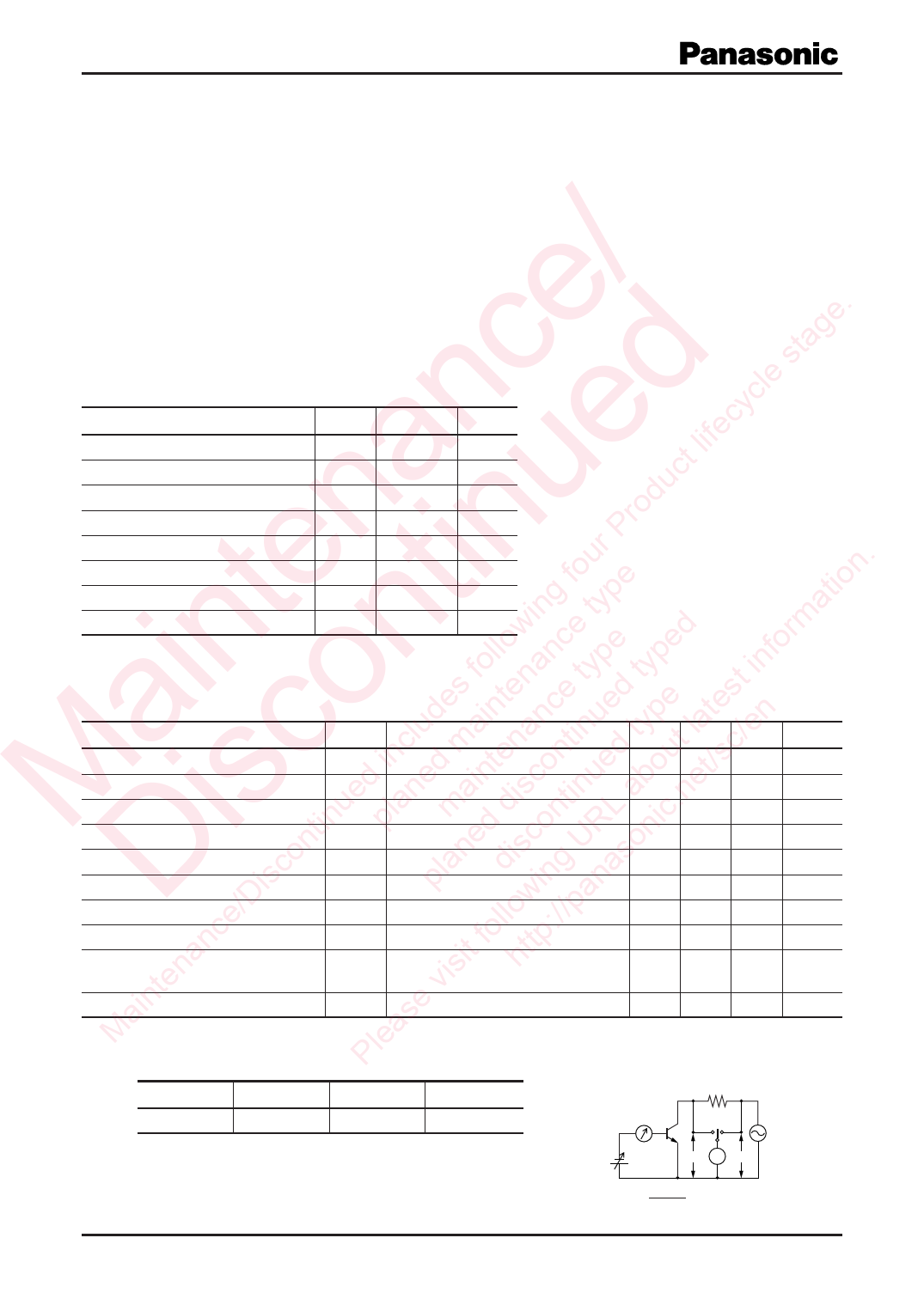
*3: Ron Measuremet circuit
Rank
R
S
T
1 kΩ
hFE
200 to 350 300 to 500 400 to 800
IB = 1 mA
VB VV VA
f = 1 kHz
V = 0.3 V
Ron =
VB
VA − VB
× 1 000 (Ω)
Publication date: May 2007
SJC00378AED
1
Share Link: 