AT89C51AC2 View Datasheet(PDF) - Atmel Corporation
Part Name
Description
Manufacturer
AT89C51AC2 Datasheet PDF : 121 Pages
| |||
A/T89C51AC2
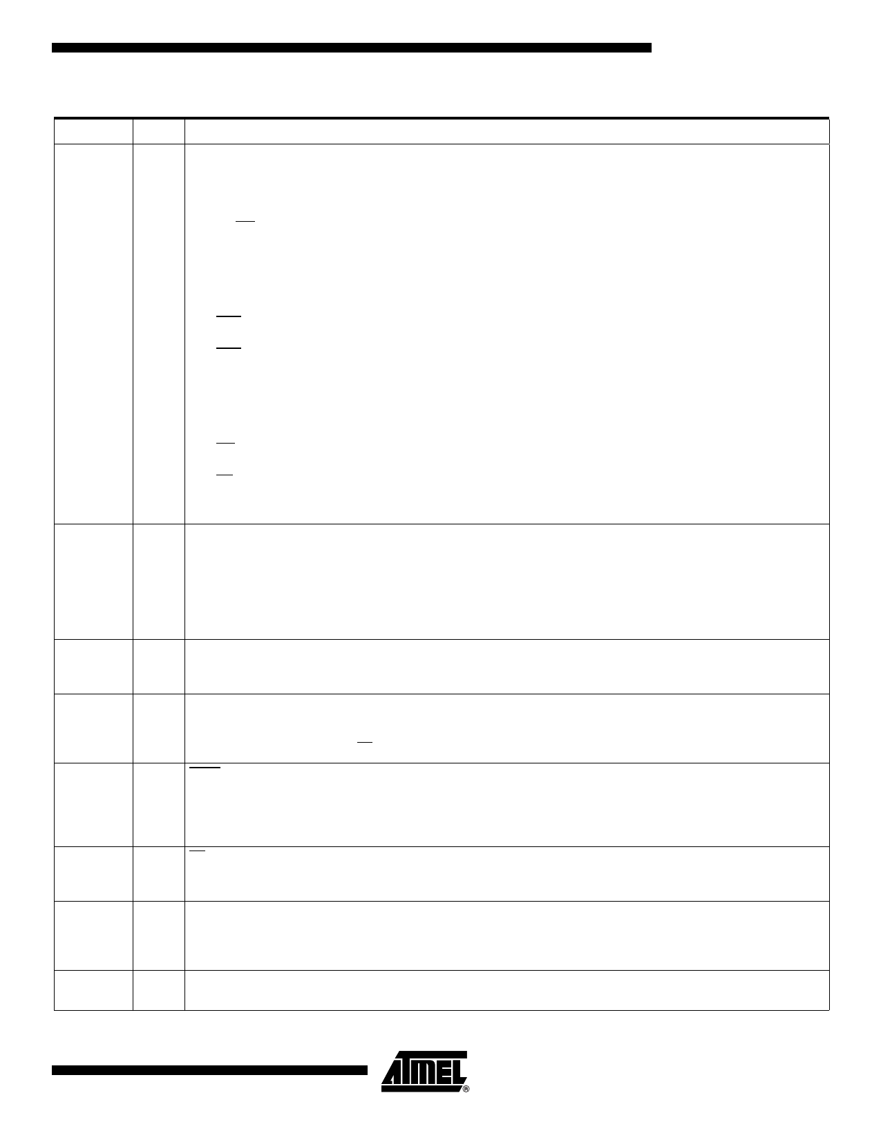
Table 1. Pin Description (Continued)
Pin Name Type Description
P3.0:7
I/O Port 3:
Is an 8-bit bi-directional I/O port with internal pull-ups. Port 3 pins that have 1’s written to them are pulled high by the internal
pull-up transistors and can be used as inputs in this state. As inputs, Port 3 pins that are being pulled low externally will be a
source of current (IIL, see section "Electrical Characteristic") because of the internal pull-ups.
The output latch corresponding to a secondary function must be programmed to one for that function to operate (except for
TxD and WR). The secondary functions are assigned to the pins of port 3 as follows:
P4.0:1
RESET
ALE
PSEN
EA
XTAL1
XTAL2
P3.0/RxD:
Receiver data input (asynchronous) or data input/output (synchronous) of the serial interface
P3.1/TxD:
Transmitter data output (asynchronous) or clock output (synchronous) of the serial interface
P3.2/INT0:
External interrupt 0 input/timer 0 gate control input
P3.3/INT1:
External interrupt 1 input/timer 1 gate control input
P3.4/T0:
Timer 0 counter input
P3.5/T1:
Timer 1 counter input
P3.6/WR:
External Data Memory write strobe; latches the data byte from port 0 into the external data memory
P3.7/RD:
External Data Memory read strobe; Enables the external data memory.
It can drive CMOS inputs without external pull-ups.
I/O Port 4:
Is an 2-bit bi-directional I/O port with internal pull-ups. Port 4 pins that have 1’s written to them are pulled high by the internal
pull-ups and can be used as inputs in this state. As inputs, Port 4 pins that are being pulled low externally will be a source of
current (IIL, on the datasheet) because of the internal pull-up transistor.
P4.0
P4.1:
It can drive CMOS inputs without external pull-ups.
Reset:
I/O A high level on this pin during two machine cycles while the oscillator is running resets the device. An internal pull-down
resistor to VSS permits power-on reset using only an external capacitor to VCC.
ALE:
O
An Address Latch Enable output for latching the low byte of the address during accesses to the external memory. The ALE is
activated every 1/6 oscillator periods (1/3 in X2 mode) except during an external data memory access. When instructions are
executed from an internal Flash (EA = 1), ALE generation can be disabled by the software.
PSEN:
The Program Store Enable output is a control signal that enables the external program memory of the bus during external
O fetch operations. It is activated twice each machine cycle during fetches from the external program memory. However, when
executing from of the external program memory two activations of PSEN are skipped during each access to the external Data
memory. The PSEN is not activated for internal fetches.
EA:
I When External Access is held at the high level, instructions are fetched from the internal Flash when the program counter is
less then 8000H. When held at the low level,A/T89C51AC2 fetches all instructions from the external program memory.
XTAL1:
I
Input of the inverting oscillator amplifier and input of the internal clock generator circuits.
To drive the device from an external clock source, XTAL1 should be driven, while XTAL2 is left unconnected. To operate
above a frequency of 16 MHz, a duty cycle of 50% should be maintained.
O
XTAL2:
Output from the inverting oscillator amplifier.
5
4127H–8051–02/08
Share Link: 