ADM1021A(2012) View Datasheet(PDF) - ON Semiconductor
Part Name
Description
Manufacturer
ADM1021A Datasheet PDF : 16 Pages
| |||
ADM1021A
Layout Considerations
Digital boards can be electrically noisy environments, and
because the ADM1021A is measuring very small voltages
from the remote sensor, care must be taken to minimize
noise induced at the sensor inputs. The following
precautions should be taken:
1. Place the ADM1021A as close as possible to the
remote sensing diode. Provided that the worst
noise sources, such as clock generators,
data/address buses, and CRTs, are avoided, this
distance can be four to eight inches.
2. Route the D+ and D− tracks close together, in
parallel, with grounded guard tracks on each side.
Provide a ground plane under the tracks, if
possible.
3. Use wide tracks to minimize inductance and
reduce noise pickup. 10 mil track minimum width
and spacing is recommended.
4. Try to minimize the number of copper/solder
joints, which can cause thermocouple effects.
Where copper/solder joints are used, ensure they
are in both the D+ and D− paths and at the same
temperature.
Thermocouple effects should not be a major
problem as 1C corresponds to about 240 mV, and
thermocouple voltages are about 3 mV/C of
temperature difference. Unless there are two
thermocouples with a big temperature differential
between them, thermocouple voltages should be
much less than 240 mV.
5. Place a 0.1 mF bypass capacitor close to the VDD
pin, and 2,200 pF input filter capacitors across D+,
D− close to the ADM1021A.
6. If the distance to the remote sensor is more than
eight inches, the use of twisted pair cable is
recommended. This works up to about 6 to 12 feet.
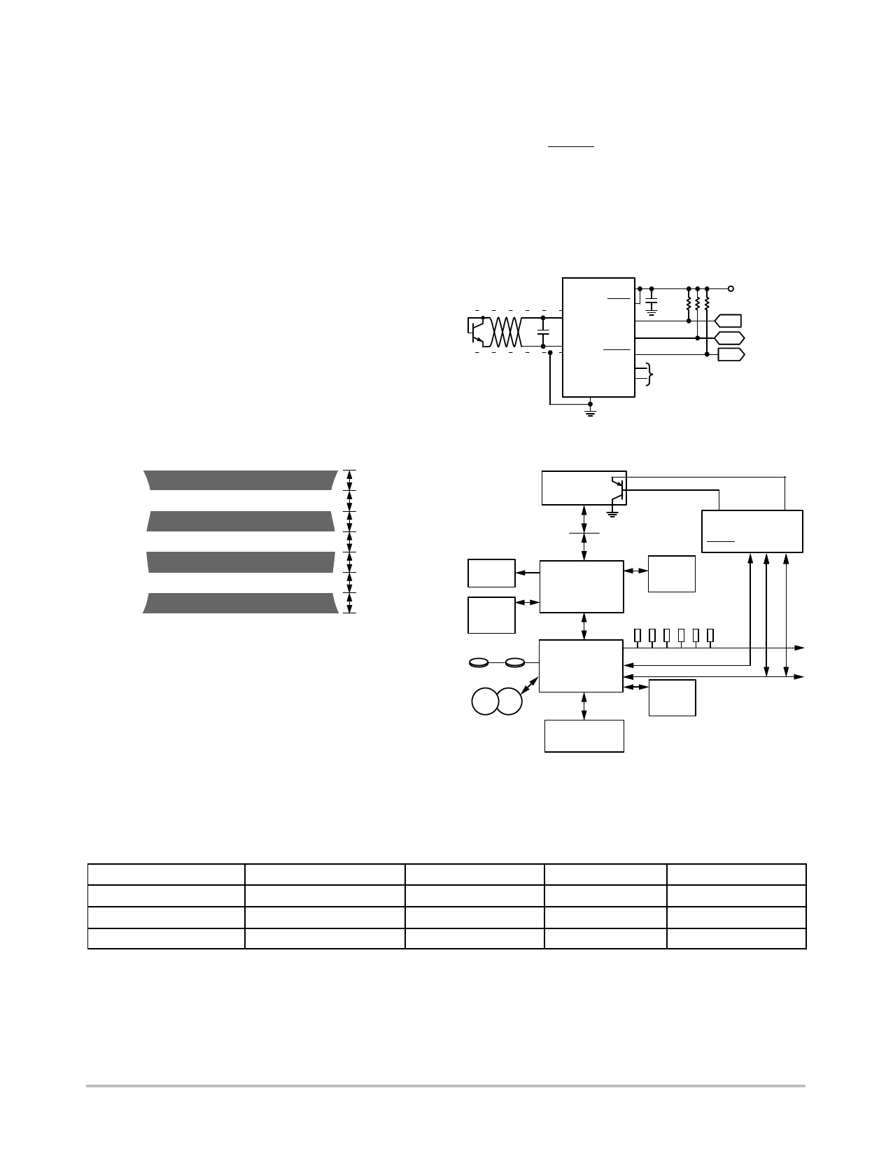
ADM1021A
VDD
STBY
2N3904
C1*
SHIELD
* C1 IS OPTIONAL
D+
SCLK
SDATA
D−
ALERT
ADD0
ADD1
GND
7. For very long distances (up to 100 feet), use
shielded twisted pair, such as Belden #8451
microphone cable. Connect the twisted pair to D+
and D− and the shield to GND close to the
ADM1021A. Leave the remote end of the shield
unconnected to avoid ground loops.
GND
D+
D−
GND
10 MIL
10 MIL
10 MIL
10 MIL
10 MIL
10 MIL
10 MIL
Figure 18. Arrangement of Signal Tracks
Because the measurement technique uses switched
current sources, excessive cable and/or filter capacitance
can affect the measurement. When using long cables, the
filter capacitor can be reduced or removed.
Cable resistance can also introduce errors. A series
resistance of 1 W introduces about 1C error.
Application Circuits
Figure 19 shows a typical application circuit for the
ADM1021A, using a discrete sensor transistor connected
via a shielded, twisted pair cable. The pullups on SCLK,
SDATA, and ALERT are required only if they are not
already provided elsewhere in the system.
The SCLK and SDATA pins of the ADM1021A can be
interfaced directly to the SMBus of an I/O chip. Figure 20
shows how the ADM1021A might be integrated into a
system using this type of I/O controller.
0.1 mF
3.3 V
ALL 10 kW
IN
I/O
OUT
TO CONTROL
CHIP
SET TO REQUIRED
ADDRESS
Figure 19. Typical Application Circuit
http://onsemi.com
14
Share Link: 