ADM1021AARQZ-R View Datasheet(PDF) - ON Semiconductor
Part Name
Description
Manufacturer
ADM1021AARQZ-R Datasheet PDF : 15 Pages
| |||
ADM1021A
corresponding low temperature limit, then one or more of
these flags are set. Bit 2 is a flag that is set if the remote
temperature sensor is open−circuit. These five flags are
NOR’d together so that if any of them are high, the ALERT
interrupt latch is set and the ALERT output goes low. Reading
the status register clears the five flag bits, provided the error
conditions that caused the flags to be set have gone away.
While a limit comparator is tripped due to a value register
containing an out−of−limit measurement, or the sensor is
open−circuit, the corresponding flag bit cannot be reset. A
flag bit can only be reset if the corresponding value register
contains an in−limit measurement, or the sensor is good.
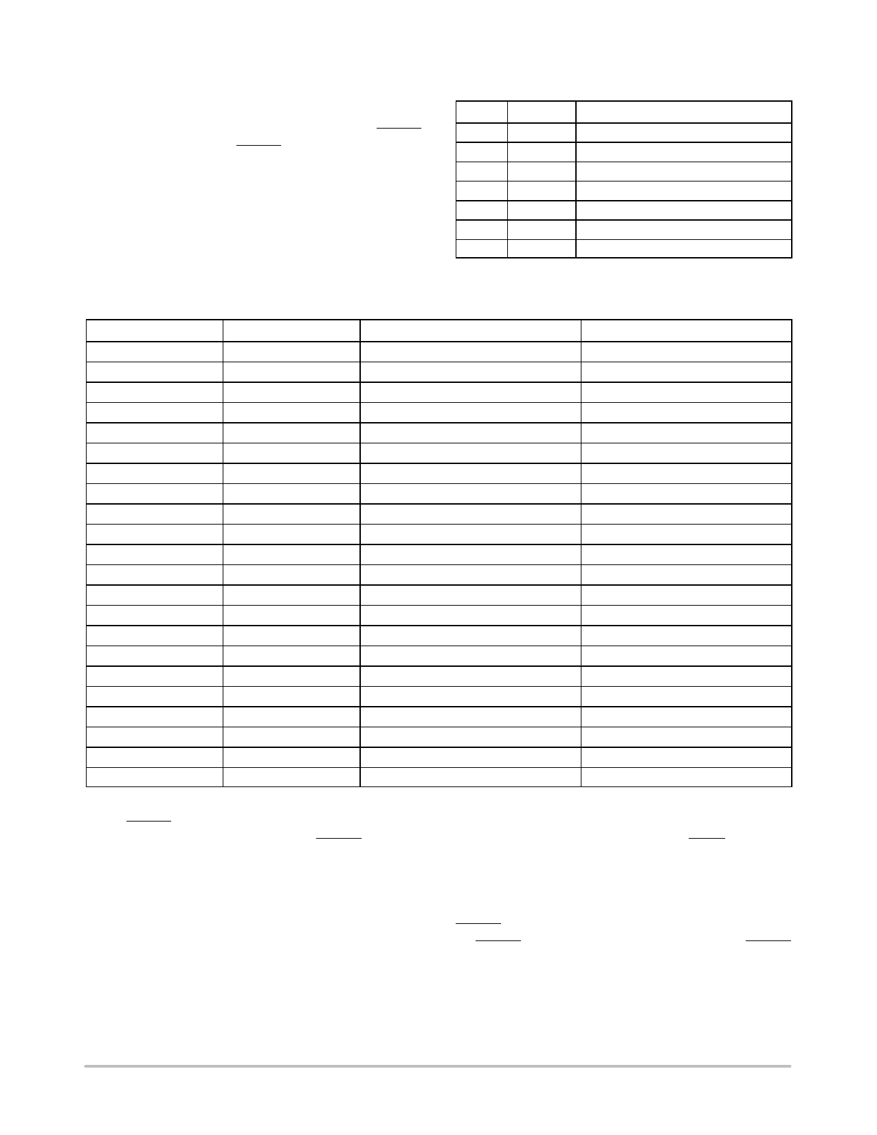
Table 2. Status Register Bit Assignments
Bit
Name
Function
7
BUSY
1 when ADC converting
6
LHIGH* 1 when local high temp limit tripped
5
LLOW* 1 when local low temp limit tripped
4
RHIGH* 1 when remote high temp limit tripped
3
RLOW* 1 when remote low temp limit tripped
2
OPEN* 1 when remote sensor open−circuit
1 to 0
Reserved
*These flags stay high until the status register is read or they are
reset by POR.
Table 3. List of ADM1021A Registers
Read Address (Hex) Write Address (Hex)
Name
Power−On Default
Not applicable
Not applicable
Address pointer
Undefined
00
Not applicable
Local temperature value
1000 0000 (0x80) (−128°C)
01
Not applicable
Remote temperature value
1000 0000 (0x80) (−128°C)
02
Not applicable
Status
Undefined
03
09
Configuration
0000 0000 (0x00)
04
0A
Conversion rate
0000 0010 (0x02)
05
0B
Local temperature high limit
0111 1111 (0x7F) (+127°C)
06
0C
Local temperature low limit
1100 1001 (0xC9) (−55°C)
07
0D
Remote temperature high limit
0111 1111 (0x7F) (+127°C)
08
0E
Remote temperature low limit
1100 1001 (0xC9) (−55°C)
Not applicable
0F (Note 1)
One−shot
10
Not applicable
Reserved
Reserved for future versions
11
11
Remote temperature offset
0000 0000 (0°C)
12
12
Reserved
Reserved for future versions
13
13
Reserved
Reserved for future versions
14
14
Reserved
Reserved for future versions
15
16
Reserved
Reserved for future versions
17
18
Reserved
Reserved for future versions
19
Not applicable
Reserved
Reserved for future versions
20
21
Reserved
Reserved for future versions
FE
Not applicable
Manufacturer device ID
0100 0001 (0x41)
FF
Not applicable
Die revision code
0011 xxxx (0x3x)
1. Writing to Address 0F causes the ADM1021A to perform a single measurement. It is not a data register and data written to it is irrelevant.
The ALERT interrupt latch is not reset by reading the
status register, but is reset when the ALERT output is
serviced by the master reading the device address, provided
the error condition has gone away and the status register flag
bits have been reset.
Configuration Register
Two bits of the configuration register are used. If Bit 6 is 0,
which is the power−on default, the device is in operating
mode with the ADC converting. If Bit 6 is set to 1, the device
is in standby mode and the ADC does not convert. Standby
mode can also be selected by taking the STBY pin low. In
standby mode, the values stored in the remote and local
temperature registers remain at the values they were when
the part was placed in standby.
Bit 7 of the configuration register is used to mask the
ALERT output. If Bit 7 is 0, which is the power−on default,
the ALERT output is enabled. If Bit 7 is set to 1, the ALERT
output is disabled.
http://onsemi.com
9
Share Link: 