AT89S2051 View Datasheet(PDF) - Atmel Corporation
Part Name
Description
Manufacturer
AT89S2051 Datasheet PDF : 45 Pages
| |||
10. Reset
During reset, all I/O Registers are set to their initial values, the port pins are weakly pulled to
VCC, and the program starts execution from the Reset Vector, 0000H. The AT89S2051/S4051
has three sources of reset: power-on reset, brown-out reset, and external reset.
10.1
Power-On Reset
A Power-On Reset (POR) is generated by an on-chip detection circuit. The detection level is
nominally 1.4V. The POR is activated whenever VCC is below the detection level. The POR cir-
cuit can be used to trigger the start-up reset or to detect a supply voltage failure in devices
without a brown-out detector. The POR circuit ensures that the device is reset from power-on.
When VCC reaches the Power-on Reset threshold voltage, the Pierce Oscillator is enabled (if the
XTAL Oscillator Bypass fuse is OFF). Only after VCC has also reached the BOD (brown-out
detection) level (see Section 10.2 ”Brown-out Reset”), the BOD delay counter starts measuring a
2-ms delay after which the Internal Reset is deasserted and the microcontroller starts executing.
The built-in 2-ms delay allows the VCC voltage to reach the minimum 2.7V level before execut-
ing, thus guaranteeing the maximum operating clock frequency. The POR signal is activated
again, without any delay, when VCC falls below the POR threshold level. A Power-On Reset (i.e.
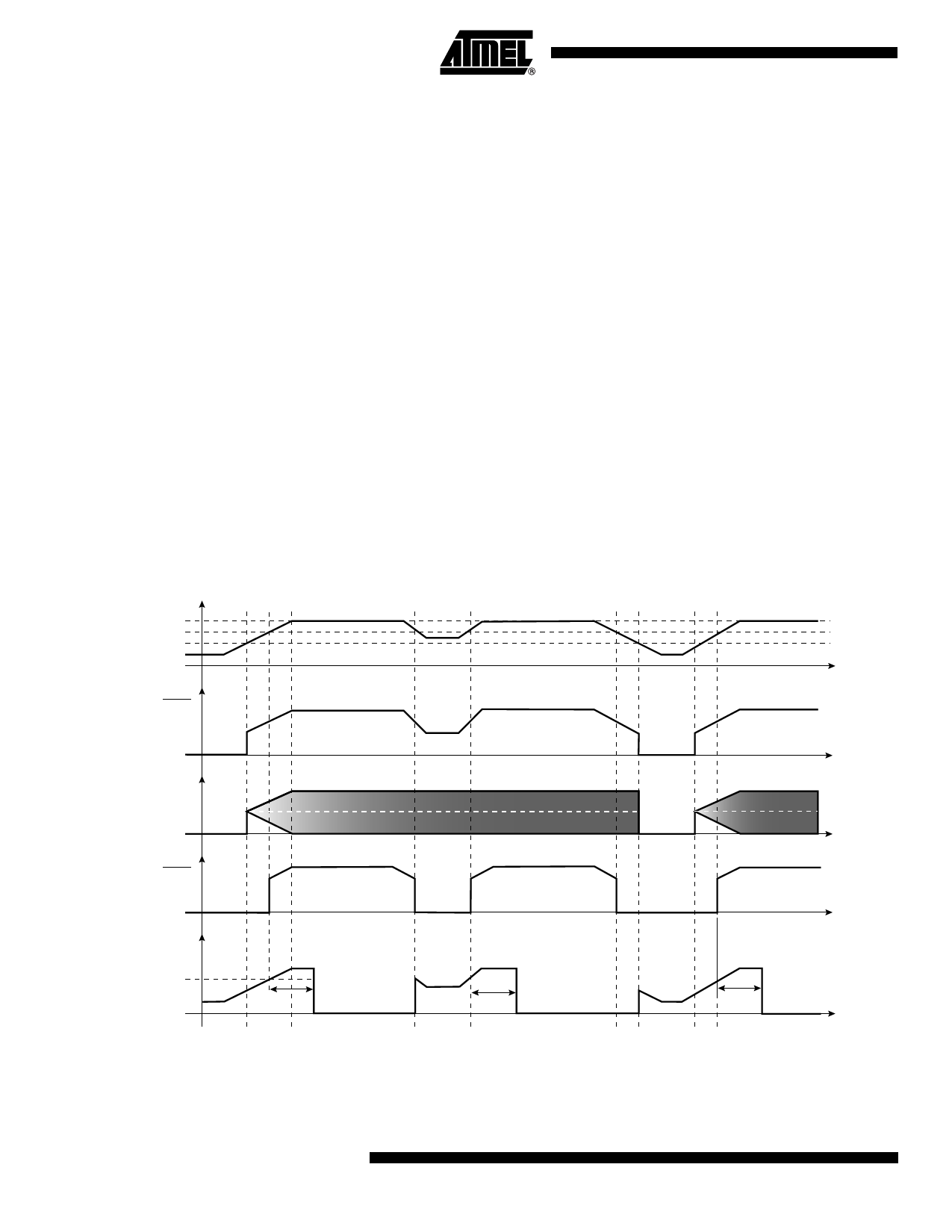
a cold reset) will set the POF flag in PCON. Refer to Figure 10-1 for details on the POR/BOD
behavior.
Figure 10-1. Power-up and Brown-out Detection Sequence
VCC
Min VCC Level 2.7V
BOD Level 2.3V
POR Level 1.4V
t
POR
XTAL1
2.4V
BOD
Internal
RESET
0
tPOR
(2 ms)
1.2V
tPOR
(2 ms)
t
t
t
tPOR
(2 ms)
t
8 AT89S2051/S4051
3390C–MICRO–7/05
Share Link: 