FX465 View Datasheet(PDF) - CML Microsystems Plc
Part Name
Description
Manufacturer
FX465 Datasheet PDF : 9 Pages
| |||
Specification ......
Characteristics
See Note
Min.
Typ.
Max.
Unit
Audio Switch
Isolation
5
-
60.0
-
dB
Serial/Parallel Inputs
Parallel Set-Up Time (tSP)
Load/Latch Pulse Width (tL)
Serial Clock Pulse Width (t )
C
Serial Set-Up Time (tSS)
Serial Data Hold Time (tH)
Serial Enable Time (t1)
Serial Load/Latch Set-up Time (t )
2
Serial Clock Frequency
400
-
400
-
400
-
400
-
400
-
400
-
400
-
-
1.0
-
ns
-
ns
-
ns
-
ns
-
ns
-
ns
-
ns
-
MHz
Notes
1.
2.
3.
4.
5.
6.
7.
8.
9.
10.
11.
12.
13.
14.
15.
16.
Refers to Rx/Tx, PTL, Decode Comparator Input, D0, D1, D2, D3, D4, D5 inputs.
All logic outputs.
Composite Signal Test condition.
Any programming tone and RL = 10kΩ. CL = 15pF.
With an input level of 0dB at 1.0kHz.
fO > 100Hz, (for 100Hz >fO >67Hz: t = (100/fO Hz) x 250ms).
Measured in a 30kHz bandwidth.
With an input level of -3.5dB at 1.0kHz
Per TIA/EIA-603.
Per TIA/EIA-603, device will not decode adjacent TIA/EIA-603 tones.
Tone output level is proportional to V .
DD
fO = 156.7Hz at -20dB.
Typically 12.5 tone cycles + 40ms
Typically 7 tone cycles + 90ms.
Max composite signal is 3.5dB with: Noise (band limited 6kHz Gaussian) -12dB to 1kHz test tone F
0
CTCSS tone -20dB ref to 1kHz test tone.
For maximum dynamic range, set audio level to 0dB, VDD x 150mVrms, using minimumVDD under
which system is intended to work. e.g. for a 2.7 to 3.3 volt system use 0dB equal to 405mVrms.
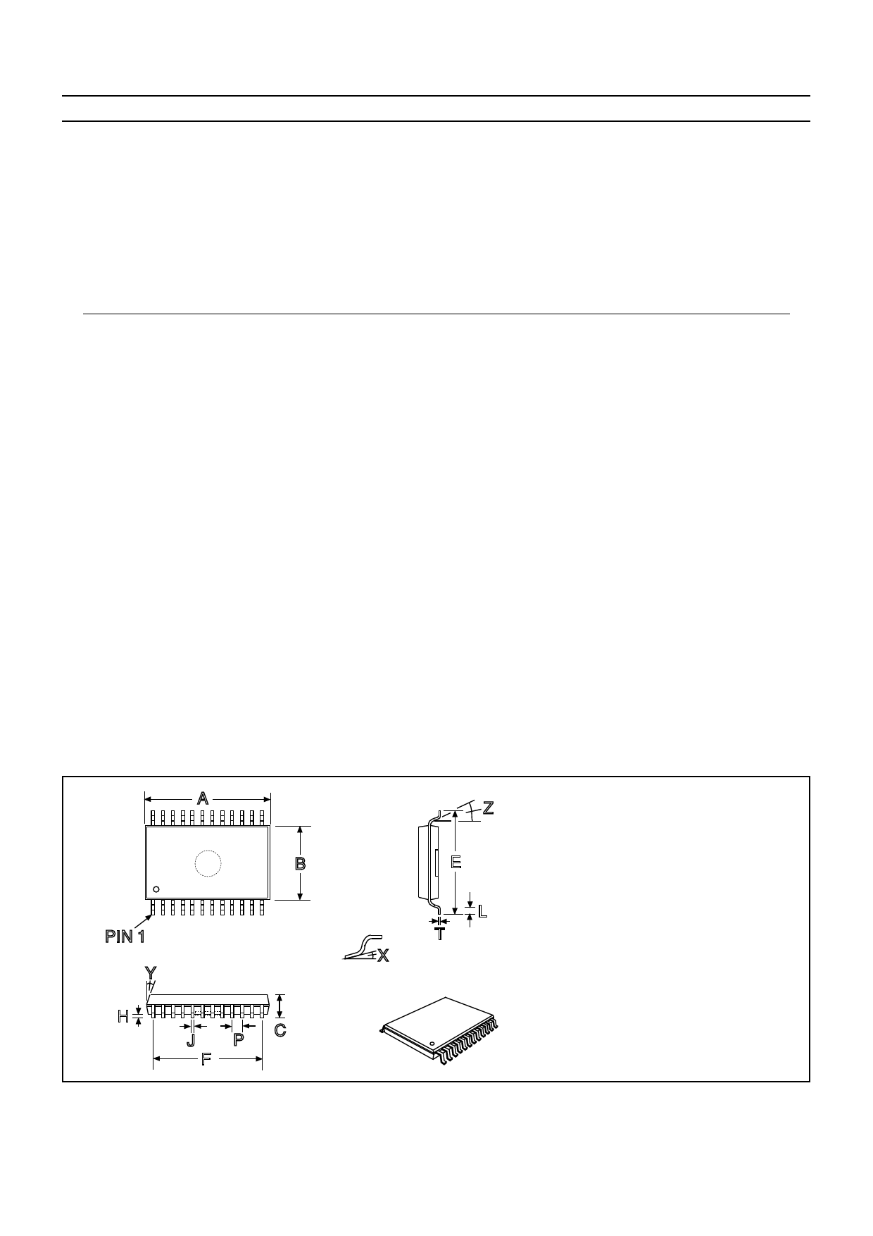
Package Outlines
The FX465 is available in the package styles outlined
below. Pin 1 identification marking is shown on the
relevant diagram and pins on all package styles number
anti-clockwise when viewed from the top.
FX465 D5 24-pin plastic S.S.O.P.
A
B
PIN 1
X
Y
H
J
PC
F
Handling Precautions
The FX465 is a CMOS LSI circuit which includes input
protection. However precautions should be taken to
prevent static discharges which may cause damage.
Z
E
L
T
DIM. MIN. TYP. MAX.
A 0.318 (8.07)
B 0.205 (5.20)
C 0.068 (1.73)
E 0.301 (7.65)
0.328 (8.33)
0.212 (5.38)
0.078 (1.99)
0.311 (7.90)
F
0.286 (7.15)
H 0.002 (0.05)
0.008 (0.21)
J 0.010 (0.25)
0.015 (0.38)
L 0.022 (0.55)
0.037 (0.95)
P
0.026 (0.65)
T 0.005 (0.13)
0.009 (0.22)
X
0°
8°
Y
7°
9°
Z
4°
10°
NOTE : All dimensions in inches (mm.)
Angles in degrees
Ordering Information
FX465 D5 24-pin plastic S.S.O.P. (D5)
CML does not assume any responsibility for the use of any circuitry described. No circuit patent licences are implied
and CML reserves the right at any time without notice to change the said circuitry.
Share Link: 