MC13135 View Datasheet(PDF) - Motorola => Freescale
Part Name
Description
Manufacturer
MC13135 Datasheet PDF : 16 Pages
| |||
MC13135 MC13136
TEST CIRCUIT INFORMATION
Although the MC13136 can be operated with a ceramic
discriminator, the recovered audio measurements for both
the MC13135 and MC13136 are made with an LC quadrature
detector. The typical recovered audio will depend on the
external circuit; either the Q of the quad coil, or the RC
matching network for the ceramic discriminator. On the
MC13136, an external capacitor between Pins 13 and 14 can
be used with a quad coil for slightly higher recovered audio.
See Figures 10 through 13 for additional information.
Since adding a matching circuit to the RF input increases
the signal level to the mixer, the third order intercept (TOI)
point is better with an unmatched input (50 Ω from Pin 21 to
Pin 22). Typical values for both have been included in the
Electrical Characterization Table. TOI measurements were
taken at the pins with a high impedance probe/spectrum
analyzer system. The first mixer input impedance was
measured at the pin with a network analyzer.
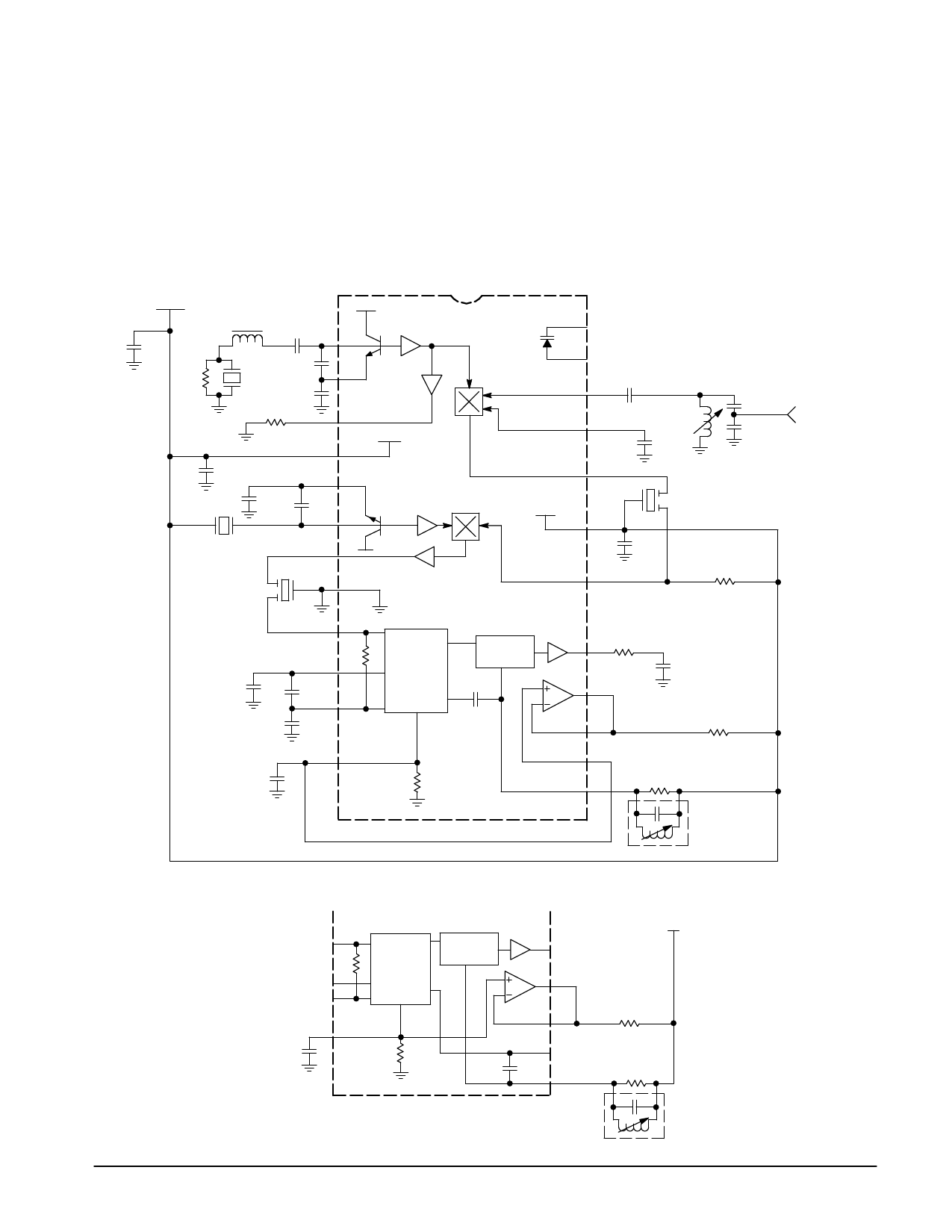
Figure 1a. MC13135 Test Circuit
VCC
0.1
1.0 k
0.84 µH
0.01
39.0 20 p
MHz
Xtal 5.0 p
5.0 k
1st LO
1
2
3
VCC1
4
24
Varicap
23
22
21
Figure 1.
0.001
0.2 µH
0.01
62 pF
RF
180 p
Input
0.1
120 p
5
50 p
6
2nd LO
20
VCC2
19
Ceramic
Filter
10.7 MHz
10.245
7
MHz Xtal
Ceramic
8
Filter
455 kHz
9
10
0.1
0.1
11
0.1
Limiter
0.1
18
Demod
AF
17
16
15
8.2 k
0.1
360
39 k
12
14
0.1
13
39 k
455 kHz
Quad
Coil
Figure 1b. MC13136 Quad Detector Test Circuit
AF
VCC
Demod
Limiter
16
12
0.1
15
39 k
14
13
39 k
455 kHz
Quad Coil
MOTOROLA ANALOG IC DEVICE DATA
3
Share Link: 