INT200TFI2 View Datasheet(PDF) - Power Integrations, Inc
Part Name
Description
Manufacturer
INT200TFI2
Power Integrations, Inc

INT200TFI2 Datasheet PDF : 12 Pages
| |||
INT200 Functional Description
5 V Regulator
The 5 V linear regulator circuit provides
the supply voltage for the control logic
and high-voltage level shift circuit. This
allows the logic section to be directly
compatible with 5 V CMOS logic
without the need of an external 5 V
supply.
Undervoltage Lockout
The undervoltage lockout circuit disables
the LS OUT pin and both HSD pins
whenever the V power supply falls
DD
below typically 9.0 V, and maintains
this condition until the VDD power supply
rises above typically 9.35 V. This
guarantees that both MOSFETs will
remain off during power-up or fault
conditions.
HSD1/HSD2
The HSD1 and HSD2 outputs are
connected to integrated high-voltage N-
channel MOSFET transistors which
perform the level-shifting function for
communication to the high-side driver.
Controlled current capability allows the
drain voltage to float with the high-side
driver. Two individual channels produce
a true differential communication
channel for accurately controlling the
high-side driver in the presence of fast
moving high-voltage waveforms.
Pulse Circuit
The pulse circuit provides the two high-
voltage level shifters with precise timing
signals. Two pulses are sent over HSD1
to signal the high-side driver to turn on.
One pulse is sent over HSD2 to signal
the high-side driver to turn off. The
combination of differential
communication with the precise timing
provides maximum immunity to noise.
INT200
Conduction Latch
An RS latch prevents the low-side driver
and high-side driver from being on at the
same time, regardless of the input signals.
.
Delay Circuit
The delay circuit matches the low-side
propagation delay with the combination
of the pulse circuit, high voltage level
shift, and high-side driver propagation
delays. This ensures that the low-side
driver and high-side driver will never be
on at the same time during switching
transitions in either direction.
Driver
The CMOS drive circuit provides drive
power to the gate of the MOSFET used
on the low side of the half bridge circuit.
The driver consists of a CMOS buffer
capable of driving an external transistor
gate at up to 15 V.
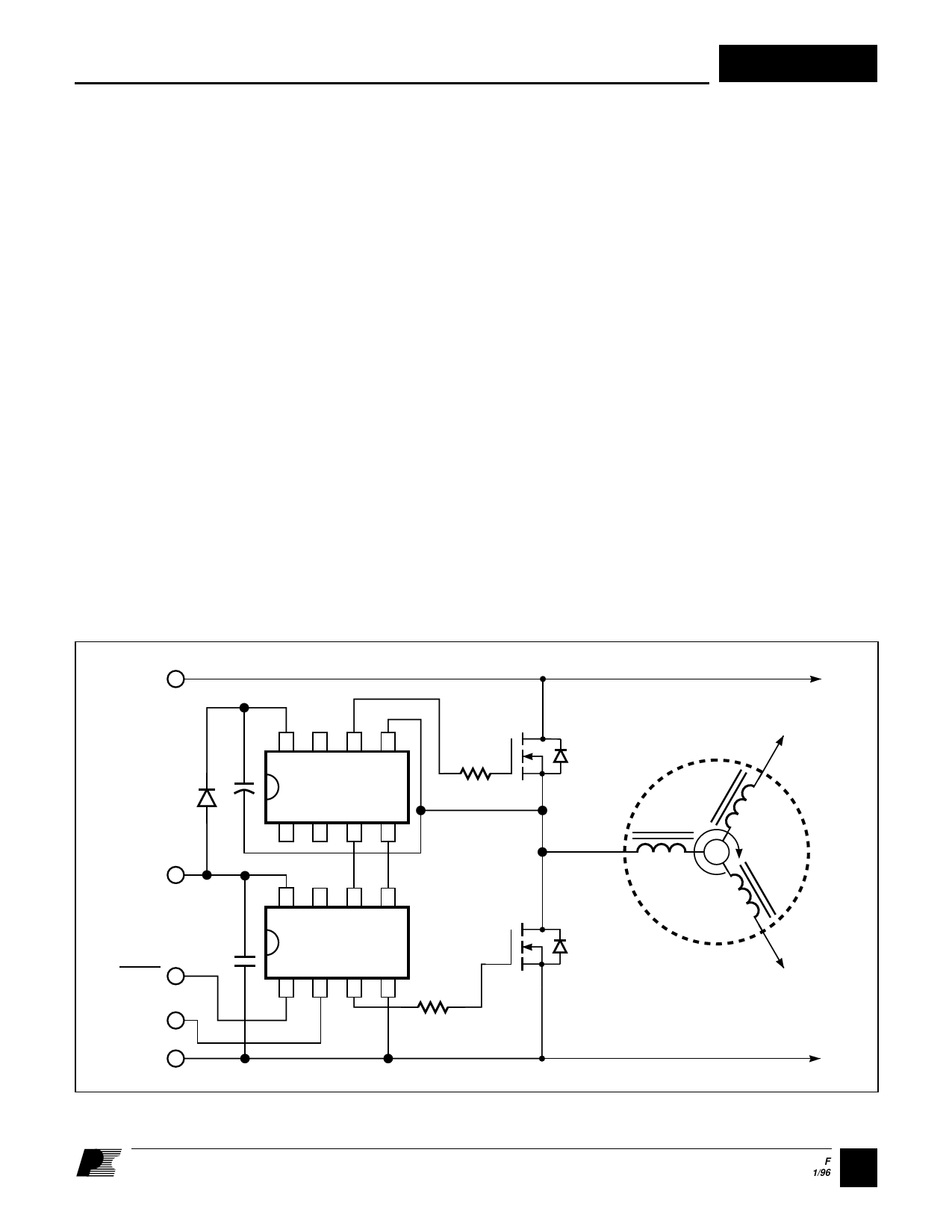
HV+
C2
D1
VDD
C1
HS IN
LS IN
HV-
8
76
5
R2
INT201
1
23
4
8
76
5
INT200
1
23
4
R1
Figure 4. Using the INT200 and INT201 in a 3-phase Configuration.
Q2
PHASE 2
PHASE 1
Q1
3-PHASE
BRUSHLESS
DC MOTOR
PHASE 3
PI-1461-042695
3 F
1/96
Share Link: