LT1166 View Datasheet(PDF) - Linear Technology
Part Name
Description
Manufacturer
LT1166 Datasheet PDF : 16 Pages
| |||
LT1166
APPLICATIONS INFORMATION
Overvoltage Protection
The supplies VTOP (Pin 1) and VBOTTOM (Pin 4) have clamp
diodes that turn on when they exceed ±12V. These diodes
act as ESD protection and serve to protect the LT1166
when used with large power MOS devices that produce
high VGS voltage. Current into Pin 1 or Pin 4 should be
limited to ±75mA maximum.
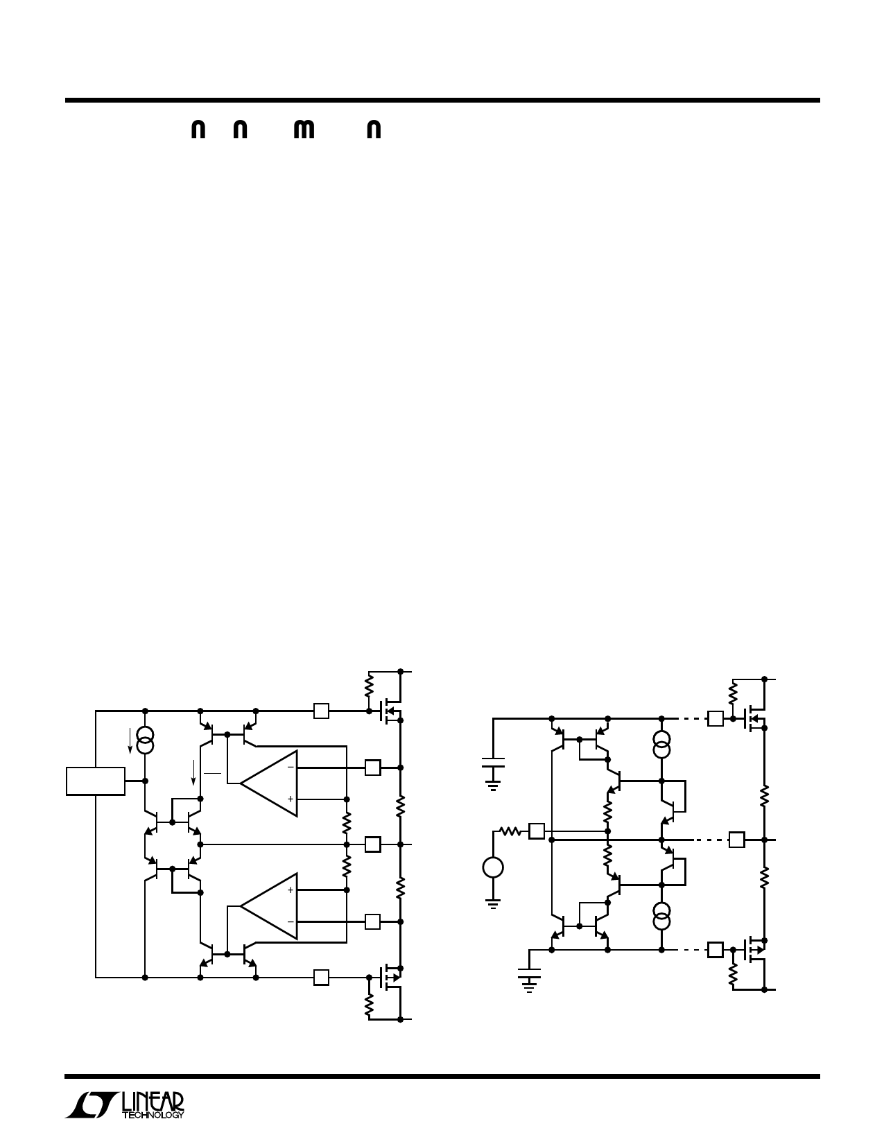
Multiplier Operation
Figure 2 shows the current multiplier circuit internal to the
LT1166 and how it works in conjunction with power
output transistors. The supply voltages VT (top) and VB
(bottom) of the LT1166 are set by the required “on”
voltage of the power devices. A reference current IREF sets
a constant VBE7 and VBE8. This voltage is across emitter
base of Q9 and Q10 which are 1/10 the emitter area of Q7
and Q8. The expression for this current multiplier is:
VBE7 + VBE8 = VBE9 + VBE10
or in terms of current:
(IC9)(IC10) = (IREF)2/100 = Constant
The product of IC9 and IC10 is constant. These currents are
mirrored and set the voltage on the (+) inputs of a pair of
VTOP
V+
RT
1k
1
M1
IREF
IREF
SHUNT
10
REGULATOR
Q7
Q9
× 10
×1
Q8
Q10
× 10
×1
8
VAB+
1Ω
1k
3
VO
1k
VAB–
1Ω
5
4
VBOTTOM
Figure 2. Constant Product Generator
M2
RB
1k
V–
1166 • F02
internal op amps. The feedback of the op amps force the
same voltage on the (–) inputs and these voltages then
appear on the sense resistors in series with the power
devices. The product of the two currents in the power
devices is constant, as one increases the other decreases.
The excellent logging nature of Q9 and Q10 allows this
relation to hold over many decades in current.
The total current in Q7 and Q8 is actually the sum of IREF
and a small error current from the shunt regulator. During
high output current conditions the error current from the
regulator decreases. Current conducted by the regulator
also decreases allowing VT or VB to increase by an amount
needed to drive the power devices.
Driving the Input Stage
Figure 3 shows the input transconductance stage of the
LT1166 that provides a way to drive VT and VB. When a
positive voltage VIN is applied to RIN, a small input current
flows into R2 and the emitter of Q2. This effect causes VO
to follow VIN within the gain error of the amplifier. The
input current is then mirrored by Q3/Q4 and current
supplied to Q4’s collector is sourced by power device M1.
The signal current in Q4’s emitter is absorbed by external
resistor RB and this causes VB to rise by the same amount
Q6
× 32
CEXT1
RIN
2
VIN
VTOP
1
V+
RT
1k
M1
Q5
×1
Q1
R1 Q11
R2 Q12
Q2
1Ω
3
VO
1Ω
Q4
× 32
CEXT2
Q3
×1
4
VBOTTOM
M2
RB
1k
V–
1166 • F03
Figure 3. Input Stage Driving Gates
5
Share Link: 