M1025-1026 View Datasheet(PDF) - Analog Devices
Part Name
Description
Manufacturer
M1025-1026 Datasheet PDF : 16 Pages
| |||
ADM1025/ADM1025A
Pin
No. Mnemonic
1 SDA
2 SCL
3 GND
4 VCC
5 VID0
6 VID1
7 VID2
8 VID3
9 D–/NTI
10 D+
11 12 VIN/VID4
12 5 VIN
13 3.3 VIN
14 2.5 VIN
15 VCCPIN
16 ADD/RST/INT/NTO
PIN FUNCTION DESCRIPTIONS
Description
Digital I/O. Serial bus bidirectional data. Open-drain output.
Digital Input. Serial bus clock.
System Ground.
Power. Can be powered by +3.3 V standby power if monitoring in low power states is required.
This pin also serves as the analog input to monitor VCC.
Digital Input. Core voltage ID readouts from the processor. This value is read into the VID0–VID3
Status Register. It has an on-chip 100 kΩ pull-up resistor (ADM1025 only).
Digital Input. Core voltage ID readouts from the processor. This value is read into the VID0–VID3
Status Register. It has an on-chip 100 kΩ pull-up resistor (ADM1025 only).
Digital Input. Core voltage ID readouts from the processor. This value is read into the VID0–VID3
Status Register. It has an on-chip 100 kΩ pull-up resistor (ADM1025 only).
Digital Input. Core voltage ID readouts from the processor. This value is read into the VID0–VID3
Status Register. It has an on-chip 100 kΩ pull-up resistor (ADM1025 only).
Analog/Digital Input. Connected to cathode of external temperature sensing diode. If held high at
power-up, initiates NAND tree test mode.
Analog Input. Connected to anode of external temperature sensing diode.
Programmable Analog/Digital Input. Defaults to 12 VIN analog input at power-up, but may be pro-
grammed as VID4 Core Voltage ID readout from the processor. This value is read into the VID4
Status Register. In analog 12 VIN mode it has an on-chip voltage attenuator. In VID4 mode it has an
on-chip 300 kΩ pull-up resistor.
Analog Input. Monitors 5 V supply.
Analog Input. Monitors 3.3 V supply.
Analog Input. Monitors 2.5 V supply.
Analog Input. Monitors processor core voltage (0 V to 3.0 V).
Programmable Digital I/O. The lowest order programmable bit of the SMBus Address, sampled on
SMB activity as a three-state input. Can also be configured to give a minimum 20 ms low reset
output pulse. Alternatively, can be programmed as an interrupt output for temperature/voltage
interrupts. Functions as the output of the NAND tree in NAND tree test mode.
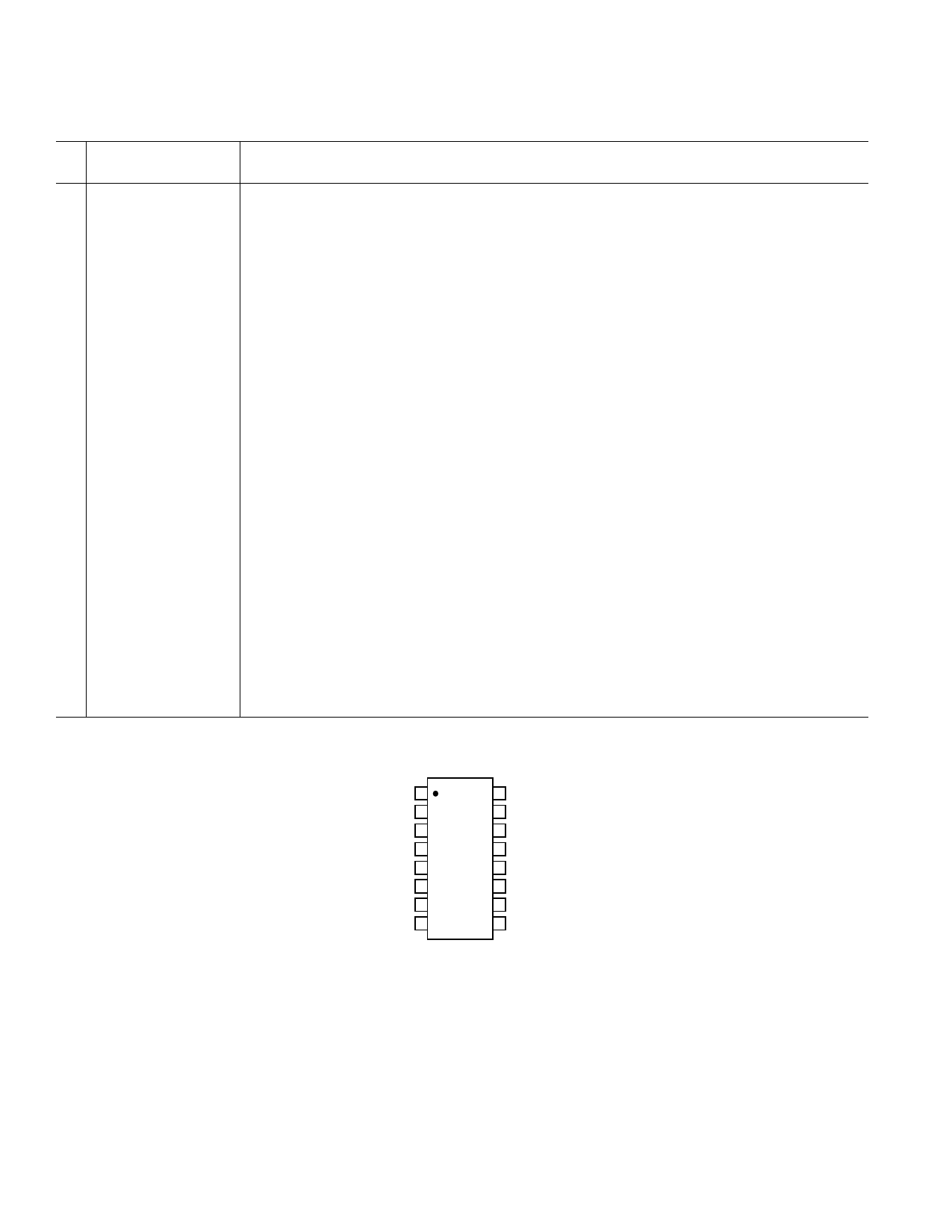
PIN CONFIGURATION
SDA 1
16 ADD/RST/INT/NTO
SCL 2
15 VCCPIN
GND 3 ADM1025/ 14 2.5VIN
VCC 4 ADM1025A 13 3.3VIN
VID0
5
TOP VIEW
(Not to Scale) 12
5VIN
VID1 6
11 12VIN/VID4
VID2 7
10 D+
VID3 8
9 D–/NTI
–4–
REV. A
Share Link: 