M52042FP View Datasheet(PDF) - Renesas Electronics
Part Name
Description
Manufacturer
M52042FP Datasheet PDF : 14 Pages
| |||
M52042FP
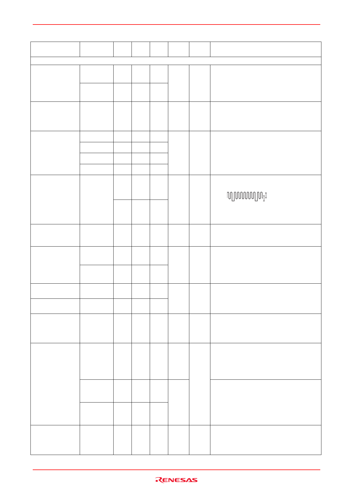
Electrical Characteristics (cont.)
Item
Chroma section
Acc control
characteristics
Symbol Min Typ Max Unit
Cacc (+4)
0 0.7 1.5 dB
Cacc (–20) –6.0 –2.0 0
Killer operation Ckilr
–53 –49 –43 dB
Color control
characteristics
Cast (4)
Cast (3)
2 2.2 4.5 dB
1.5 2.0 4.0
Cast (1)
–8.5 –6 –4
Cast (0, 5) –17 –13 –10
APC pull-in range ∆fapc
+400 +600 —
Hz
— –300 –200
B demodulator
sensitivity
Demodulated
output voltage
ratio
DB
R (R/B)
R (G/B)
0.8 1.2 1.6 Vp-p
0.46 0.52 0.60 —
0.20 0.30 0.40
Killer output
voltage H
Killer output
voltage L
TINT control
variance
Vkiller H
Vkiller L
T
2.5 3.2 —
V
— 0.20 0.40
75 85 100 deg
TINT control
characteristics
Topen
–5 +5 +15 deg
Tmin
Tmax
HD for chroma
Dhd
delay
–55 40 –25 deg
+30 –40 +60
— 2.0 2.2 µs
Test
No
Test Conditions
14 Input burst 0.2 Vp-p + CW 4.33 MHz shall
be 0 dB. Measure the output at pin (12)
when the input is changed to +4 dB and –20
dB, and calculate the ratio of the measured
amplitude to the output amplitude at 0 dB.
15 Input a chroma signal of 0.2 Vp-p to the
input. Reduce the amplitude and measure
the amplitude ratio when the voltage at pin
(15) exceeds 2.5 V.
16 Input burst 0.2 Vp-p + CW 4.33 MHz,
change V20 to 2 V, 4 V, 3 V, 1 V and 0.5 V
to measure each output (100 kHz beat)
amplitude at pin (12), and calculate the ratio
between the measured amplitude and the
output amplitude at V20 = 1 V.
17 Input only SYNC, and after adjusting free
run, input 0.2 Vp-p
CW (
0.2 Vp-p ), then change
0.2 Vp-p
the frequency. Measure the frequency
when VCXO oscillator is placed in a locked
condition from the free-run condition.
18 Input CW 4.33 MHz of 0.2 Vp-p to the input,
and measure the output amplitude at pin
(12) when V20 = 1 V.
19 Input CW 4.33 MHz of 0.2 Vp-p to the input,
measure the output amplitude at pins (10),
(11) when V20 = 1 V, and calculate the ratio
of the measured amplitude to the output
amplitude in Test No.18 above.
21 Measure DC voltage at pin (15) when 0 V
and 4 V are applied to pin (18).
22 Input a chroma signal of 0.4 Vp-p to the
input, and measure the phase variance at
pin (12) when 0 V and 4 V are applied to
V19.
23 Apply B monochromatic wave, (variable
phase) 0.4 Vp-p and burst 0.2 Vp-p to the
input. Measure the input phase in which the
output at pin (12) becomes maximum with
V19 open as burst phase –180 degrees.
Apply B monochromatic wave (variable
phase) 0.4 Vp-p and burst 0.2 Vp-p to the
input. Measure the input phase in which the
output at pin (12) becomes "maximum"
when V19 is 0 V and 4 V as burst phase
–180 degrees.
24 Apply B monochromatic wave 0.4 Vp-p and
burst 0.2 Vp-p to the input. Measure the
delay time from HD pulse rise to the chroma
rise of pin (12) output.
Rev.2.00 Sep 14, 2006 page 9 of 13
Share Link: 