5KP100A View Datasheet(PDF) - General Semiconductor
Part Name
Description
Manufacturer
5KP100A Datasheet PDF : 5 Pages
| |||
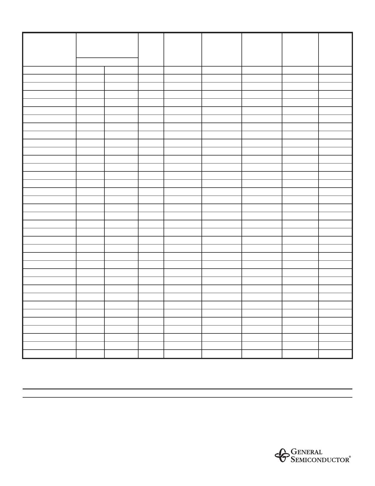
ELECTRICAL CHARACTERISTICS at (TA=25°C unless otherwise noted) TABLE 1 (Cont’d)
Device Type
5KP33
5KP33A
5KP36
5KP36A
5KP40
5KP40A
5KP43
5KP43A
5KP45
5KP45A
5KP48
5KP48A
5KP51
5KP51A
5KP54
5KP54A
5KP58
5KP58A
5KP60
5KP60A
5KP64
5KP64A
5KP70
5KP70A
5KP75
5KP75A
5KP78
5KP78A
5KP85
5KP85A
5KP90
5KP90A
5KP100
5KP100A
5KP110
5KP110A
Breakdown Voltage
V(BR)
(Volts) (NOTE 1)
MIN
MAX
36.7
44.9
36.7
40.6
40.0
48.9
40.0
44.2
44.4
54.3
44.4
49.1
47.8
58.4
47.8
52.8
50.0
61.1
50.0
55.3
53.3
65.2
53.3
58.9
56.1
69.3
56.7
62.7
60.0
73.3
60.0
66.3
64.4
78.7
64.4
71.2
66.7
81.5
66.7
73.7
71.1
96.9
71.1
78.6
77.6
95.1
77.8
86.0
83.3
102
83.3
92.1
86.7
106.0
86.7
95.8
94.4
115
94.4
104
100
122
100
111
111
136
111
123
122
149
122
135
Test
Current
at IT
(mA)
5.0
5.0
5.0
5.0
5.0
5.0
5.0
5.0
5.0
5.0
5.0
5.0
5.0
5.0
5.0
5.0
5.0
5.0
5.0
5.0
5.0
5.0
5.0
5.0
5.0
5.0
5.0
5.0
5.0
5.0
5.0
5.0
5.0
5.0
5.0
5.0
Stand-off
Voltage
VWM
(Volts)
33.0
33.0
36.0
36.0
40.0
40.0
43.0
43.0
45.0
45.0
48.0
48.0
51.0
51.0
54.0
54.0
58.0
58.0
60.0
60.0
64.0
64.0
70.0
70.0
75.0
75.0
78.0
78.0
85.0
85.0
90.0
90.0
100
100
110
110
Maximum
Reverse
Leakage
at VWM
ID (µA)
10.0
10.0
10.0
10.0
10.0
10.0
10.0
10.0
10.0
10.0
10.0
10.0
10.0
10.0
10.0
10.0
10.0
10.0
10.0
10.0
10.0
10.0
10.0
10.0
10.0
10.0
10.0
10.0
10.0
10.0
10.0
10.0
10.0
10.0
10.0
10.0
Maximum
Peak Pulse
Current
IPPM
(NOTE 2)
(Amps)
84.7
93.8
77.8
86.1
70.0
77.5
65.2
72.0
62.3
68.8
58.5
64.6
54.9
60.7
51.9
57.4
48.5
53.4
46.7
51.7
43.9
48.5
40.0
44.2
37.3
41.3
36.0
39.7
33.1
36.5
31.3
34.2
27.9
30.9
25.5
28.2
Maximum
Clamping
Voltage at
IPPM
VC (Volts)
59.0
53.3
64.3
58.1
71.4
64.5
76.7
69.4
80.3
72.7
85.5
77.4
91.1
82.4
96.3
87.1
103
94
107
97
114
103
125
113
134
121
139
126
151
137
160
146
179
162
196
177
Maximum
Temperature
Coefficient
of V(BR)
(% / °C)
0.104
0.104
0.104
0.104
0.105
0.105
0.105
0.105
0.106
0.106
0.106
0.106
0.107
0.107
0.107
0.107
0.107
0.107
0.108
0.108
0.108
0.108
0.108
0.108
0.108
0.108
0.108
0.108
0.108
0.110
0.110
0.110
0.110
0.110
0.112
0.112
NOTES:
(1) V(BR) measured after IT applied for 300µs IT=square wave pulse or equivalent
(2) Surge current waveform per Fig. 3 and derate per Fig. 2
(3) All items and symbols are consistent with ANSI/IEEE C62.35
APPLICATION
The 5KP series of high power transient voltage suppressors were designed to be used on the output of switching power supplies. These devices may be used to replace
crowbar circuits. Both the 5 and 10 percent voltage tolerances are referenced to the power supply output voltage level.
They are able to withstand high levels of peak current while allowing a circuit breaker to trip or a fuse blow before shorting. This will enable the user to reset the breaker or
replace the fuse and continue operation. For this type operation, it is recommended that a sufficient mounting surface be used for dissipating the heat generated by the
Transient Voltage Suppressor during the transient or over-voltage condition.
Transient Voltage Suppressors are Silicon PN Junction devices designed for absorption of high voltage transients associated with power disturbances, switching and
induced lighting effects. This series is available from 5.0 volts thru 110 volts.
Share Link: 