MSP3410D View Datasheet(PDF) - Micronas
Part Name
Description
Manufacturer
MSP3410D Datasheet PDF : 83 Pages
| |||
MSP 34x0D
PRELIMINARY DATA SHEET
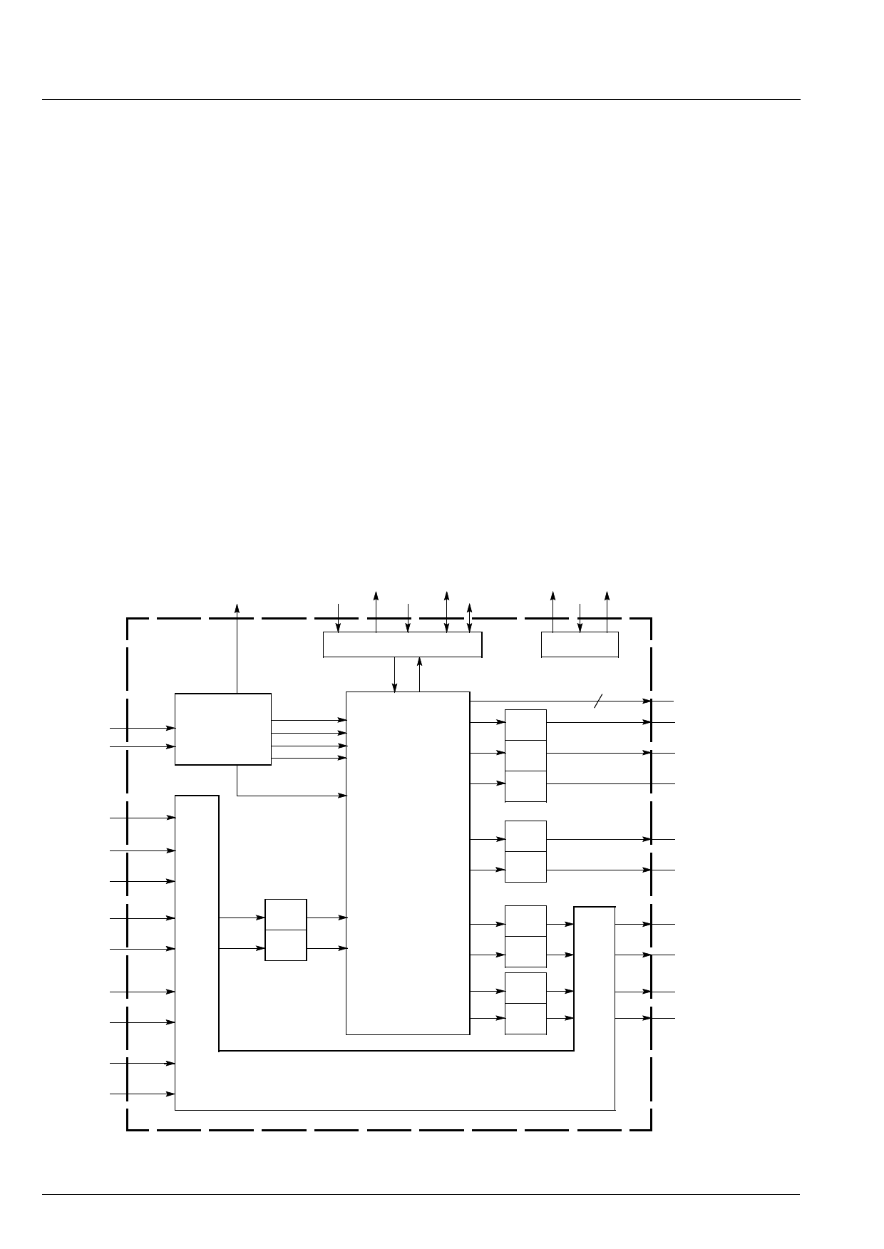
4. Architecture of the MSP 34x0D
Fig. 4–1 shows a simplified block diagram of the IC. Its
architecture is split into three main functional blocks:
1. demodulator and NICAM decoder section
2. digital signal processing (DSP) section performing
audio baseband processing
3. analog section containing two A/D-converters,
nine D/A-converters, and SCART Switching Facili-
ties.
4.1. Demodulator and NICAM Decoder Section
4.1.1. Analog Sound IF – Input Section
The input pins ANA_IN1+, ANA_IN2+, and ANA_IN−
offer the possibility to connect two different sound IF
(SIF) sources to the MSP 34x0D. By means of bit [8] of
AD_CV (see Table 6–5 on page 25), either terrestrial
or satellite sound IF signals can be selected. The ana-
log-to-digital conversion of the preselected sound IF
signal is done by an A/D converter whose output is
used to control an analog automatic gain circuit (AGC)
providing an optimal level for a wide range of input lev-
els. It is possible to switch between automatic gain
control and a fixed (setable) input gain. In the optimal
case, the input range of the A/D converter is com-
pletely covered by the sound IF source. Some combi-
nations of SAW filters and sound IF mixer ICs, how-
ever, show large picture components on their outputs.
In this case, filtering is recommended. It was found,
that the high-pass filters formed by the coupling capac-
itors at pins ANA_IN1+ and ANA_IN2+ and the IF
impedance (as shown in the application diagram) are
sufficient in most cases.
Sound IF
ANA_IN1+
ANA_IN2+
Mono
MONO_IN
SC1_IN_L
SCART1
SC1_IN_R
SC2_IN_L
SCART2
SC2_IN_R
SC3_IN_L
SCART3
SC3_IN_R
SC4_IN_L
SCART4
SC4_IN_R
ADR-Bus
I2S_DA_OUT
I2S_CL
I2S_DA_IN1 I2S_DA_IN2 I2S_WS
AUD_CL_OUT XTAL_OUT
XTAL_IN
Demodulator
& NICAM
Decoder
A/D
A/D
I2S Interface
I2S1/2L/R I2S_L/R
FM1/AM
FM2
NICAM A
NICAM B
LOUD-
SPEAKER L
LOUD-
SPEAKER R
IDENT
SUBWOOFER
DSP
HEADPHONE L
HEADPHONE R
SCARTL
SCARTR
SCART1_L
SCART1_R
SCART2_L
SCART2_R
Crystal PLL
2
D/A
D/A
D/A
D/A
D/A
D/A
D/A
D/A
D/A
D_CTR_OUT0/1
DACM_L
Loudspeaker
DACM_R
DACM_SUB
Subwoofer
DACA_L
Headphone
DACA_R
SC1_OUT_L
SCART 1
SC1_OUT_R
SC2_OUT_L
SCART 2
SC2_OUT_R
SCART Switching Facilities
Fig. 4–1: Architecture of the MSP 34x0D
10
Micronas
Share Link: 